MF-R005-0 Bourns Inc., MF-R005-0 Datasheet - Page 5
MF-R005-0
Manufacturer Part Number
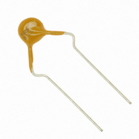
MF-R005-0
Description
FUSE PTC RESET 50MA HOLD
Manufacturer
Bourns Inc.
Series
MF-Rr
Type
PTC Resettable Fusesr
Datasheet
1.MF-R110.pdf
(6 pages)
Specifications of MF-R005-0
R Min/max
7.300 ~ 11.10 Ohm
Voltage - Max
60V
Time To Trip
5s
Current - Hold (ih) (max)
50mA
Current - Trip (it)
100mA
Current - Max
40A
Package / Case
Radial
Hold Current
0.05 Amp
Trip Current
0.1 Amp
Current Rating (max)
40 Amps
Resistance
11.1 Ohms
Maximum Voltage
60 VoltsDC
Termination Style
Radial
Mounting Style
Through Hole
Current Rating
40 Amps
Dimensions
8 mm L x 3.1 mm W x 8.3 mm H x 8 mm D
Lead Spacing
5.1 mm
Operating Temperature Range
- 40 C to + 85 C
Initial Resistance (min)
7.3Ohm
Initial Resistance (max)
11.1Ohm
Voltage Rating Max
60V
Trip Time (max)
5@0.5As
Power Dissipation (typ)
0.22W
Post Trip Resistance (max)
22Ohm
Agency Approvals
CSA
Operating Temperature Min Deg. C
-40C
Operating Temperature Max Deg. C
85C
Holding Current
50mA
Tripping Current
100mA
Initial Resistance Max
11.1ohm
Operating Voltage
60V
Ptc Fuse Case
Radial Leaded
External Depth
3.1mm
External Width
7.4mm
Rohs Compliant
Yes
Lead Free Status / RoHS Status
Lead free / RoHS Compliant
Lead Free Status / RoHS Status
Lead free / RoHS Compliant, Lead free / RoHS Compliant
Other names
MF-R005
MF-R005
MF-R005


Devices taped using EIA468–B/IEC286-2 standards. See table below and Figures 1 and 2 for details.
Dimension Description
Carrier tape width
Hold down tape width
Hold down tape
Top distance between tape edges
Sprocket hole position
Sprocket hole diameter
Abscissa to plane (straight lead)
Abscissa to plane (kinked lead)
Abscissa to top (straight lead)
Abscissa to top (kinked lead)
Overall width w/lead protrusion (straight lead)
Overall width w/lead protrusion (kinked lead)
Overall width w/o lead protrusion (straight lead)
Overall width w/o lead protrusion (kinked lead)
Lead protrusion
Protrusion of cutout
Protrusion beyond hold-down tape
Sprocket hole pitch
Pitch tolerance
Device pitch: MF-R005–MF-R160, MF-R/90,
MF-RX110/72–MF-RX185/72
Device pitch: MF-R185–MF-R400, MF-RX110–MF-RX375
MF-R/600, MF-RX250/72–MF-RX375/72
Tape thickness
Tape thickness with splice: MF-R010–MF-R160,
MF-RX110/72–MF-RX185/72
Tape thickness with splice: MF-R250–MF-R1100,
MF-RX110–MF-RX375, MF-R/90, MF-RX250/72-MF-RX375/72
Splice sprocket hole alignment
Body lateral deviation
Body tape plane deviation
Customers should verify actual device performance in their specifi c applications.
Specifi cations are subject to change without notice.
MF-R, MF-R/90, MF-R/600, MF-RX, MF-RX/72 & MF-RX/250 Series
Tape and Reel Specifi cations
Mark
IEC
W 0
W 2
W 1
D 0
H 0
H 1
H 1
Δ p
P 0
Δ h
W
I 1
I 2
H
L
t
Mark
EIA
W 4
W 6
W 5
D 0
H 0
H 1
H 1
C 1
C 1
C 2
C 2
P 0
Δ p
L 1
Δ h
W
H
I 2
t 1
t 1
L
t
20 consecutive
No protrusion
Not specifi ed
Dimensions
(1.496)
(1.268)
(2.165)
(2.126)
(1.673)
(.709)
(.433)
(.118)
(.354)
(.157)
(.728)
(.039)
(.433)
(.035)
(.059)
(.091)
18.5
(.63)
38.0
(1.7)
54.0
42.5
12.7
(0.5)
(0.5)
(1.0)
32.2
55.0
43.2
12.7
25.4
1.5
2.3
18
16
1.0
0.9
11
11
3
9
4
0
0
0
Dimensions
DIMENSIONS:
(-0.02/+.039)
(-0.02/+0.03)
-0.5/+0.75
Tolerance
-0.5/+1.0
(±.0078)
(±.118)
(±.012)
(±.039)
(±.012)
(±.024)
(±.012)
(±.039)
(±.051)
(±.02)
max.
max.
max.
max.
max.
max.
max.
max.
max.
max.
max.
max.
±0.2
±3.0
±0.5
±0.3
±0.3
±0.6
±0.3
±1.0
±1.3
min.
±1
(INCHES)
MM
Related parts for MF-R005-0
Image
Part Number
Description
Manufacturer
Datasheet
Request
R

Part Number:
Description:
PTC RESETTABLE .50A 13.2V 1206
Manufacturer:
Bourns Inc.
Datasheet:

Part Number:
Description:
PTC RESETTABLE .12A 30V 1206
Manufacturer:
Bourns Inc.
Datasheet:

Part Number:
Description:
FUSE RESETTABLE .35A HOLD SMD
Manufacturer:
Bourns Inc.
Datasheet:

Part Number:
Description:
FUSE PTC RESETTABLE SMD 0805
Manufacturer:
Bourns Inc.
Datasheet:

Part Number:
Description:
FUSE RESETTABLE 1.25A 15V SMD
Manufacturer:
Bourns Inc.
Datasheet:

Part Number:
Description:
FUSE RESETTABLE .50A 60V SMD
Manufacturer:
Bourns Inc.
Datasheet:

Part Number:
Description:
FUSE RESETTABLE 1.0A 30V SMD
Manufacturer:
Bourns Inc.
Datasheet:

Part Number:
Description:
FUSE RESETTABLE .75A 30V SMD
Manufacturer:
Bourns Inc.
Datasheet:
Part Number:
Description:
FUSE RESETTABLE .30A 60V SMD
Manufacturer:
Bourns Inc.
Datasheet:

Part Number:
Description:
FUSE RESETTABLE 2.0A 15V SMD
Manufacturer:
Bourns Inc.
Datasheet:

Part Number:
Description:
FUSE RESETTABLE 2.5A 15V SMD
Manufacturer:
Bourns Inc.
Datasheet:

Part Number:
Description:
FUSE PTC RESET 1.60A HOLD
Manufacturer:
Bourns Inc.
Datasheet:
Part Number:
Description:
FUSE PTC RESET 3.00A HOLD
Manufacturer:
Bourns Inc.
Datasheet:

Part Number:
Description:
FUSE RESETTABLE .05A 30V HLD SMD
Manufacturer:
Bourns Inc.
Datasheet:

Part Number:
Description:
FUSE RESETTABLE .50A 13.2V SMD
Manufacturer:
Bourns Inc.
Datasheet: