LP38855S-1.2/NOPB National Semiconductor, LP38855S-1.2/NOPB Datasheet
LP38855S-1.2/NOPB
Specifications of LP38855S-1.2/NOPB
LP38855S-1.2


Related parts for LP38855S-1.2/NOPB


LP38855S-1.2/NOPB Summary of contents
Page 1
... Shutdown Current: 1 µA (typical) I IN(GND) Precision Output Voltage: ±1.0% for T ≤ ≤ for 0°C T +125°C, across all line and load conditions J Typical Application Circuit © 2007 National Semiconductor Corporation Features ■ Standard V ■ Wide V BIAS ■ Stable with 10 µF ceramic capacitors provides BIAS ■ ...
Page 2
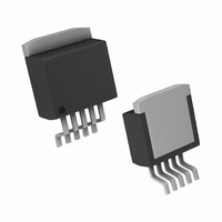
... Ordering Information V * Order Number OUT LP38855S-0.8 0.8V LP38855SX-0.8 LP38855T-0.8 LP38855S-1.2 1.2V LP38855SX-1.2 LP38855T-1.2 * For custom V values between 0.8V and 1.2V please contact the National Semiconductor Sales Office. OUT Connection Diagrams TO-263, Top View Pin Descriptions Pin # Pin Symbol GND 4 OUT 5 BIAS ...
Page 3
... Absolute Maximum Ratings If Military/Aerospace specified devices are required, please contact the National Semiconductor Sales Office/ Distributors for availability and specifications. Storage Temperature Range Lead Temperature Soldering, 5 seconds ESD Rating Human Body Model (Note 2) Power Dissipation (Note 3) V Supply Voltage (Survival Supply Voltage (Survival) ...
Page 4
Symbol Parameter ENABLE Pin I ENABLE pin Current EN V Enable Voltage Threshold EN(ON) V Enable Voltage Hysteresis EN(HYS) t Turn-OFF Delay Time OFF t Turn-ON Delay Time ON AC Parameters PSRR Ripple Rejection for Voltage ...
Page 5
Typical Performance Characteristics V = 3.0V mA BIAS OUT IN OUT V Ground Pin Current (I BIAS GND(BIAS) V Ground Pin Current (I IN GND(IN) Dropout Voltage ( Temperature DO Unless otherwise ...
Page 6
V vs Temperature OUT Enable Thresholds (V EN Enable Pull-Up Resistor (r www.national.com 20202667 ) vs Temperature Enable Pull-Down Current (I 20202672 ) vs Temperature EN 20202674 6 UVLO Thresholds vs Temperature 20202668 ) vs Temperature EN 20202673 V Line ...
Page 7
V Line Transient Response IN V Line Transient Response BIAS = 10 μF Ceramic Load Transient Respose, C OUT V Line Transient Response BIAS 20202678 Load Transient Response, C 20202680 Load Transient Response, C 20202682 7 20202679 = 10 μF ...
Page 8
Load Transient Response, C Load Transient Response PSRR IN www.national.com = 100 μF Ceramic Load Transient Response, C OUT 20202684 = 100 μF Tantalum OUT 20202686 20202671 8 = 100 μF Tantalum OUT 20202685 V PSRR BIAS 20202670 ...
Page 9
Block Diagram 9 20202605 www.national.com ...
Page 10
Application Information EXTERNAL CAPACITORS To assure regulator stability, capacitors are required on the input, output and bias pins as shown in the Typical Application Circuit. Output Capacitor A minimum output capacitance of 10 µF, ceramic, is required for stability. The ...
Page 11
The second part is the power that is dissipated in the bias and control circuitry, and can be determined with the formula × I D(BIAS) BIAS GND(BIAS) where I is the portion of the operating ground current ...
Page 12
Physical Dimensions TO220 5-lead, Molded, Stagger Bend Package (TO220-5) TO263 5-Lead, Molded, Surface Mount Package (TO263-5) www.national.com inches (millimeters) unless otherwise noted NS Package Number T05D NS Package Number TS5B 12 ...
Page 13
Notes 13 www.national.com ...
Page 14
... National Semiconductor and the National Semiconductor logo are registered trademarks of National Semiconductor Corporation. All other brand or product names may be trademarks or registered trademarks of their respective holders. ...