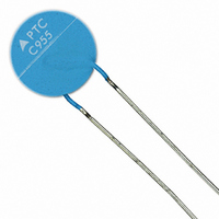
B59955C0120A070 EPCOS Inc, B59955C0120A070 Datasheet

B59955C0120A070
Specifications of B59955C0120A070
B59955C0120A070
B59955C120A70
B59955C120A70
Available stocks
Related parts for B59955C0120A070
B59955C0120A070 Summary of contents
Page 1
PTC thermistors for overcurrent protection Leaded disks, coated Series/Type: B599*0 Date: November 2009 © EPCOS AG 2009. Reproduction, publication and dissemination of this publication, enclosures hereto and the information contained therein without EPCOS' prior express consent is prohibited. ...
Page 2
... Overcurrent protection Leaded disks, coated Applications Overcurrent protection Short circuit protection Features Lead-free terminals Wide range of rated currents Manufacturer's logo and type designation stamped on in black or red for T and for T = 120 C and 130 C ref stamped on in white UL approval for T = 120 C and 130 C to ...
Page 3
Overcurrent protection Leaded disks, coated General technical data Max. operating voltage Rated voltage Switching cycles Tolerance Tolerance Operating temperature range Operating temperature range Operating temperature range Electrical specifications and ordering codes I ...
Page 4
Overcurrent protection Leaded disks, coated Reliability data Test Standard Electrical endurance, IEC 60738-1 cycling Electrical endurance, IEC 60738-1 constant Damp heat IEC 60738-1 Rapid change IEC 60738-1 of temperature Vibration IEC 60738-1 Shock IEC 60738-1 Climatic sequence IEC ...
Page 5
Overcurrent protection Leaded disks, coated Characteristics (typical) for T PTC resistance R versus PTC PTC temperature T PTC (measured at low signal voltage) Switching time t versus switching current I S (measured still air) ...
Page 6
Overcurrent protection Leaded disks, coated Characteristics (typical) for T PTC resistance R versus PTC PTC temperature T PTC (measured at low signal voltage) Switching time t versus switching current I S (measured still air) ...
Page 7
Overcurrent protection Leaded disks, coated Characteristics (typical) for T PTC resistance R versus PTC PTC temperature T PTC (measured at low signal voltage) Switching time t versus switching current I S (measured still air) ...
Page 8
Overcurrent protection Leaded disks, coated Characteristics (typical) for T PTC resistance R versus PTC PTC temperature T PTC (measured at low signal voltage) Switching time t versus switching current I S (measured still air) ...
Page 9
Overcurrent protection Leaded disks, coated Characteristics (typical) for T PTC resistance R versus PTC PTC temperature T PTC (measured at low signal voltage) Switching time t versus switching current I S (measured still air) ...
Page 10
Overcurrent protection Leaded disks, coated Characteristics (typical) for T PTC resistance R versus PTC PTC temperature T PTC (measured at low signal voltage) Switching time t versus switching current I S (measured still air) ...
Page 11
Overcurrent protection Leaded disks, coated Cautions and warnings General EPCOS thermistors are designed for specific applications and should not be used for purposes not identified in our specifications, application notes and data books unless otherwise agreed with EPCOS ...
Page 12
Overcurrent protection Leaded disks, coated Mounting Electrode must not be scratched before/during/after the mounting process. Contacts and housing used for assembly with thermistor have to be clean before mounting. Es- pecially grease or oil must be removed. When ...
Page 13
Overcurrent protection Leaded disks, coated Symbols and terms A Area C Heat capacity th f Frequency I Current I Maximum current max I Rated current R I PTC current PTC I Residual currrent r I Residual currrent in ...
Page 14
Overcurrent protection Leaded disks, coated Settling time (for level sensors Rated temperature R T Sensing temperature sense T Operating temperature op T PTC temperature PTC t Response time R T Reference temperature ref T Temperature ...
Page 15
Important notes The following applies to all products named in this publication: 1. Some parts of this publication contain statements about the suitability of our products for certain areas of application. These statements are based on our knowledge of typical ...


