U5020M-MFPG3Y Atmel, U5020M-MFPG3Y Datasheet - Page 5

U5020M-MFPG3Y
Manufacturer Part Number
U5020M-MFPG3Y
Description
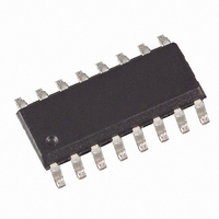
IC TIMER WATCHDOG DIGITAL 16SOIC
Manufacturer
Atmel
Type
Watchdog Circuitr
Datasheet
1.U5020M-MFP.pdf
(10 pages)
Specifications of U5020M-MFPG3Y
Number Of Voltages Monitored
1
Output
Open Drain or Open Collector
Reset
Active High
Reset Timeout
Adjustable/Selectable
Voltage - Threshold
3.8V
Operating Temperature
-40°C ~ 85°C
Mounting Type
Surface Mount
Package / Case
16-SOIC (3.9mm Width)
Lead Free Status / RoHS Status
Lead free / RoHS Compliant
4.5
4.5.1
Figure 4-3.
4.6
4.6.1
4755B–AUTO–11/05
Microcontroller in Active Mode
Microcontroller in Sleep Mode
Monitoring with the “Short” Trigger Window
Monitoring with the “Long” Trigger Window
Trigger
Reset out
Mode
V
DD
Pulse Diagram with no Trigger Pulse During the Short Watchdog Time
After the switch-over mode the watchdog operates in short watchdog mode and expects a trig-
ger pulse from the microcontroller within the defined time window, t
watchdog generates a reset pulse which resets the microcontroller if
Figure 4-3
Figure 4-4 on page 6
starts a new monitoring cycle with the disable time, t
controller, the watchdog needs to be triggered three times correctly before it sets its enable
output. This feature is used to activate or deactivate safety-critical components which have to be
switched to a certain condition (emergency status) in the case of a microcontroller malfunction.
As soon as there is an incorrect trigger sequence, the enable signal is reset and it takes a
sequence of three correct triggers before enable is reset.
The long watchdog mode allows cyclical wake-up of the microcontroller during sleep mode. As
in short watchdog mode, there is a disable time, t
nal is accepted. The watchdog can be switched from the short trigger window to the long trigger
window with a “high” potential at the mode pin (pin 12). In contrast to the short watchdog mode,
the time periods are now much longer and the enable output remains inactive so that other com-
ponents can be switched off to effect a further decrease in current consumption. As soon as a
wake-up signal at one of the 6 wake up inputs (pins 3 to 8) is detected, the long watchdog mode
ends, a reset pulse wakes-up the sleeping microcontroller and the normal monitoring cycle starts
with the mode switch-over time.
By means of a low or high potential at pin 16 (time switch), two values for the long watchdog
time can be selected.
• the trigger pulse duration is too long
• the trigger pulse is within the disable time, t
• there is no trigger pulse
t
0
shows the pulse diagram with a missing trigger pulse.
t
shows a correct trigger sequence. The positive edge of the trigger signal
1
t
2
2
4
, and an enable time, t
2
. To ensure correct operation of the micro-
t
3
5
, in which a trigger sig-
3
Pin 13
, (enable time). The
Pin 10
Pin 12
Pin 11
U5020M
5


