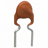
PTGL05AS100K4B51B0 Murata Electronics North America, PTGL05AS100K4B51B0 Datasheet
PTGL05AS100K4B51B0
Manufacturer Part Number
PTGL05AS100K4B51B0
Description
THERMISTOR PTC 60V 10 OHM 10%
Manufacturer
Murata Electronics North America
Series
PTGLr
Specifications of PTGL05AS100K4B51B0
Voltage - Max
60V
Current - Hold (ih) (max)
170mA
Current - Trip (it)
335mA
Current - Max
1.5A
Package / Case
Radial
Lead Free Status / RoHS Status
Lead free by exemption / RoHS Compliant
R Min/max
-
Time To Trip
-
Other names
490-3977


No.
10
11
12
1
2
3
4
5
6
7
8
9
Operating Temperature
Storage Temperature
Resistance Value (at 25°C)
Withstanding Voltage
Protective Threshold Current
Tensile Strength of Lead
Wire Terminal
Bending Strength of Lead
Wire Terminal
Solderability
Terminal Durability of
Soldering
Humidity Test
Load Test at High
Temperature
Load Cycle Test at Room
Temperature
Item
-30 to +85°C
-40 to +125°C
Satisfies ratings
No problem
Satisfies ratings
(Trip Current, Hold Current)
No damage
Lead wire does not come off
Solder is applied around the lead wire covering 3/4
or more of the circumference without gap in the axial
direction.
∆R/R25V±15%
∆R/R25V±20%
∆R/R25V±20%
∆R/R25V±20%
Rating Value
The temperature range with maximum voltage applied to the
POSISTORr.
The temperature range with zero voltage.
Resistance value is measured by applying voltage under 1.0Vdc
(by a direct current of less than 10mA) at 25°C. But it must be
measured after maximum voltage is applied for 180 seconds and
then is left for 2 hours at 25°C.
We apply AC voltage 120% that of the maximum voltage to
POSISTORr by raising voltage gradually for 180±5 seconds at
25°C. (A protective resistor is to be connected in series, and
the inrush current through POSISTORr must be limited below
maximum rated value.)
Maximum current measured in this examination. Voltage is
applied to POSISTORr in 3 minutes step by step on still air
based on "Protective Threshold Current Test Conditions"
shown in next page. Stable current is measured at each step.
The load is gradually applied to each terminal of POSISTORr
until the force of the following table in the axial direction with
fixing POSISTORr's body itself and this load is kept for 10
seconds.
POSISTORr is held so that it is perpendicular to the lead wire
with the following lead hanging in the axial direction of the lead
wire.
The lead wire is slowly bent toward 90° and returned.
Then it is slowly bent in the opposite direction and returned to
original state.
The Lead wire of POSISTORr is soaked in an Isopropyl
Alcohol (JIS K 8839) solution (about 25wt%) of colophony (JIS
K 5902) for 5-10 sec. Each lead wire is soaked in Molten solder
(JIS Z 3282 H60A) at 235±5°C from the bottom to a point of
2.0-2.5mm for 2±0.5 seconds.
The lead wire of POSISTORr is soaked in Molten solder (JIS Z
3282 H60A) at 350±10°C from the bottom to a point of 2.0-
2.5mm for 3.5±0.5 seconds.
After the device is left at room temperature (25°C) for 24±4
hours, the resistance is then measured.
POSISTORr is set in an environmental chamber at 60±2°C
and 90-95% humidity for 500±4 hours.
After the device is left at room temperature (25°C) for one hour,
the resistance measurement is then performed.
POSISTORr is set in an environmental chamber at 85±3°C
with maximum voltage applied for 500±4 hours. After the
device is left at room temperature (25°C) for one hour, the
resistance measurement is performed. (A protective resistor is
to be connected in series and the inrush current through
POSISTORr must be limited below maximum rated value.)
POSISTORr is set in a room temperature at 25±2°C with
maximum voltage applied for 1 minute and then is left without
voltage applied for 5 minutes. This cycle is repeated for 100
cycles, and after the device is left at room temperature (25°C)
for one hour, the resistance measurement is performed. (A
protective resistor is to be connected in series and the inrush
current through POSISTORr must be limited below maximum
rated value.)
Lead Diameter
Lead Diameter
ø0.60mm max.
ø0.60mm max.
ø0.65mm min.
ø0.65mm min.
Method of Examination
Continued on the following page.
Force
4.90N
9.80N
Force
2.45N
4.90N
Related parts for PTGL05AS100K4B51B0
Image
Part Number
Description
Manufacturer
Datasheet
Request
R

Part Number:
Description:
BUZZER PIEZO 25VP-P SMD
Manufacturer:
Murata Electronics North America

Part Number:
Description:
CAP 4-ARRAY 680PF 100V X7R 1206
Manufacturer:
Murata Electronics North America
Datasheet:
Part Number:
Description:
CAP 4-ARRAY 1000PF 100V X7R 1206
Manufacturer:
Murata Electronics North America
Datasheet:
Part Number:
Description:
CAP 4-ARRAY 1800PF 100V X7R 1206
Manufacturer:
Murata Electronics North America
Datasheet:
Part Number:
Description:
CAP 4-ARRAY 68000PF 16V X7R 1206
Manufacturer:
Murata Electronics North America
Datasheet:

Part Number:
Description:
CAP CER 1000PF 50V 10% X7R 0402
Manufacturer:
Murata Electronics North America
Datasheet:
Part Number:
Description:
CAP CER 10000PF 16V 10% X7R 0402
Manufacturer:
Murata Electronics North America
Datasheet:

Part Number:
Description:
CAP 5.5-25PF 2.5X3.2MM SMD
Manufacturer:
Murata Electronics North America
Datasheet:

Part Number:
Description:
CAP 4.5-20PF 2.5X3.2MM SMD
Manufacturer:
Murata Electronics North America
Datasheet:

Part Number:
Description:
CAP 5.0-20PF 3.2X4.5MM SMD RED
Manufacturer:
Murata Electronics North America
Datasheet:

Part Number:
Description:
CAP 2.0-6.0PF 3.2X4.5MM SMD BLU
Manufacturer:
Murata Electronics North America
Datasheet:

Part Number:
Description:
CAP 1.4-3.0PF 3.2X4.5MM SMD BRN
Manufacturer:
Murata Electronics North America
Datasheet:

Part Number:
Description:
CAP 3.0-10PF 3.2X4.5MM SMD WHT
Manufacturer:
Murata Electronics North America
Datasheet:

Part Number:
Description:
CAP 2.0-6.0PF 4X4.5MM TOPADJ BLU
Manufacturer:
Murata Electronics North America
Datasheet:

Part Number:
Description:
CAP 8.5-40PF 4X4.5MM TOPADJ YEL
Manufacturer:
Murata Electronics North America
Datasheet:
PTGL05AS100K4B51B0 Summary of contents
Page 1
Item No. 1 Operating Temperature -30 to +85°C 2 Storage Temperature -40 to +125°C 3 Resistance Value (at 25°C) Satisfies ratings 4 Withstanding Voltage No problem Satisfies ratings 5 Protective Threshold Current (Trip Current, Hold Current) Tensile Strength of Lead ...
Page 2
Continued from the preceding page. Protective Threshold Current Test Conditions 1. Substrate Materials: Phenol Size: 50x50xt1.6mm Land Pattern: Cu land without through hole 2. Measurement condition Solder POSISTORr on the substrate, then put the cover (150mm cubed) surround POSISTORr to ...