MF-R010 Bourns Inc., MF-R010 Datasheet

FUSE PTC RESETTABLE .1A HOLD

MF-R010

Manufacturer Part Number
MF-R010
Description
FUSE PTC RESETTABLE .1A HOLD
Manufacturer
Bourns Inc.
Series
MF-Rr
Datasheet

Specifications of MF-R010

R Min/max
2.500 ~ 4.500 Ohm
Voltage - Max
60V
Time To Trip
4s
Current - Hold (ih) (max)
100mA
Current - Trip (it)
200mA
Current - Max
40A
Package / Case
Radial
Holding Current
100mA
Tripping Current
200mA
Initial Resistance Max
4.5ohm
Operating Voltage
60V
Ptc Fuse Case
Radial Lead
Initial Resistance Min
2.5ohm
Lead Spacing
5.1mm
Brand/series
MF-R Series
Current, Rating
40 A
Dimensions
0.291x0.122 "
Mounting Type
PCB
Primary Type
Resettable
Resistance, Dc
0.25 Ohms
Termination
Radial
Voltage, Rating
60 VDC
External Depth
3.1mm
Rohs Compliant
Yes
Lead Free Status / RoHS Status
Lead free / RoHS Compliant
Lead Free Status / RoHS Status
Lead free / RoHS Compliant, Lead free / RoHS Compliant

Available stocks

Company
Part Number
Manufacturer
Quantity
Price
Part Number:
MF-R010
Manufacturer:
BOURNS
Quantity:
60 000
Part Number:
MF-R010
Manufacturer:
BOURNS/伯恩斯
Quantity:
20 000
Part Number:
MF-R010-2
Manufacturer:
KEMET
Quantity:
12 000
Part Number:
MF-R010-2-99
Manufacturer:
BOURNS/伯恩斯
Quantity:
20 000
Operating/Storage Temperature ...................... -40 °C to +85 °C
Maximum Device Surface Temperature
Passive Aging .................................................. +85 °C, 1000 hours .......................................... ±5 % typical resistance change
Humidity Aging ................................................ +85 °C, 85 % R.H. 1000 hours ........................ ±5 % typical resistance change
Thermal Shock ................................................ -40 °C to +85 °C, 10 times .............................. ±10 % typical resistance change
Solvent Resistance .......................................... MIL-STD-202, Method 215 .............................. No change
Vibration .......................................................... MIL-STD-883C, Method 2007.1, ..................... No change
Test
Visual/Mech. .................................................... Verify dimensions and materials ...................... Per MF physical description
Resistance ....................................................... In still air @ 23 °C ............................................. Rmin ≤ R ≤ Rmax
Time to Trip ...................................................... 5 times Ihold, Vmax, 23 °C .............................. T ≤ max. time to trip (seconds)
Hold Current .................................................... 30 min. at Ihold ................................................ No trip
Trip Cycle Life .................................................. Vmax, Imax, 100 cycles ................................... No arcing or burning
Trip Endurance ................................................ Vmax, 48 hours ................................................ No arcing or burning
UL File Number ............................................... E 174545
CSA File Number ............................................. CA 110338
TÜV File Number ............................................. R2057213
*RoHS Directive 2002/95/EC Jan 27 2003 including Annex.
Specifi cations are subject to change without notice.
Customers should verify actual device performance in their specifi c applications.
**CSA approval pending.
MF-R005**
MF-R010
MF-R017
MF-R020
MF-R025
MF-R030
MF-R040
MF-R050
MF-R065
MF-R075
MF-R090
MF-R090-0-9
MF-R110
MF-R135
MF-R160
MF-R185
MF-R250
MF-R250-0-10
MF-R300
MF-R400
MF-R500
MF-R600
MF-R700
MF-R800
MF-R900
MF-R1100
Test Procedures And Requirements For Model MF-R Series
Electrical Characteristics
Environmental Characteristics
in Tripped State ............................................ 125 °C
Model
0 1 8
R
1 1 0
0 T
V max.
Volts
60
60
60
60
60
60
60
60
60
60
60
30
30
30
30
30
30
30
30
30
30
30
30
30
30
16
I max.
Amps
100
40
40
40
40
40
40
40
40
40
40
40
40
40
40
40
40
40
40
40
40
40
40
40
40
40
11.00
Ihold
Hold
Condition A
Test Conditions
0.05
0.10
0.17
0.20
0.25
0.30
0.40
0.50
0.65
0.75
0.90
0.90
1.10
1.35
1.60
1.85
2.50
2.50
3.00
4.00
5.00
6.00
7.00
8.00
9.00
Features
MF-R Series - PTC Resettable Fuses
Amperes
at 23 °C
Radial Leaded Devices
Cured, fl ame retardant epoxy polymer
insulating material meets UL 94V-0
requirements
RoHS compliant*
Agency recognition:
10.00
12.00
14.00
16.00
18.00
22.00
Itrip
0.10
0.20
0.34
0.40
0.50
0.60
0.80
1.00
1.30
1.50
1.80
1.80
2.20
2.70
3.20
3.70
5.00
5.00
6.00
8.00
Trip
0.065
0.055
0.040
0.025
0.025
0.020
0.010
0.010
0.005
0.005
0.005
0.005
0.003
Min.
2.50
2.00
1.50
1.00
0.76
0.52
0.41
0.27
0.18
0.14
0.07
0.10
7.3
Resistance
at 23 °C
Ohms
Initial
0.115
0.105
0.048
0.048
Max.
11.1
4.50
3.20
2.84
1.95
1.36
0.86
0.77
0.48
0.40
0.31
0.12
0.18
0.07
0.05
0.03
0.03
0.02
0.02
0.02
0.01
0.01
1 Hour (R 1 )
Resistance
Post-Trip
at 23 °C
Accept/Reject Criteria
Ohms
0.014
Max.
22.0
7.50
8.00
4.40
3.00
2.10
1.29
1.17
0.72
0.60
0.47
0.22
0.27
0.17
0.15
0.11
0.07
0.07
0.08
0.05
0.05
0.04
0.03
0.03
0.02
Applications
Almost anywhere there is a low voltage power
supply and a load to be protected, including:
Computers & peripherals
General electronics
Automotive applications
Amperes
at 23 °C
0.85
1.25
3.25
3.75
6.75
9.25
12.5
12.5
15.0
20.0
25.0
30.0
35.0
40.0
45.0
40.0
0.5
0.5
1.0
1.5
2.0
2.5
4.5
4.5
5.5
8.0
Max. Time
to Trip
Seconds
at 23 °C
***20.0
10.3
10.3
10.8
12.7
14.5
16.0
17.5
18.8
20.0
5.0
4.0
3.0
2.2
2.5
3.0
3.8
4.0
5.3
6.3
7.2
5.9
6.6
7.3
8.0
8.7
***Tested at 40 amps
Dissipation
at 23 °C
Tripped
Power
Watts
0.22
0.38
0.48
0.40
0.45
0.50
0.55
0.75
0.90
0.90
1.00
0.60
0.70
0.80
0.90
1.00
1.20
1.20
2.00
2.50
3.00
3.50
3.80
4.00
4.20
4.50
Typ.

Related parts for MF-R010

MF-R010 Summary of contents

Page 1

... Electrical Characteristics I max. V max. Model Volts Amps MF-R005 MF-R010 60 40 MF-R017 60 40 MF-R020 60 40 MF-R025 60 40 MF-R030 60 40 MF-R040 60 40 MF-R050 60 40 MF-R065 60 40 MF-R075 60 40 MF-R090 60 40 MF-R090-0 MF-R110 30 40 MF-R135 30 40 MF-R160 30 40 MF-R185 30 40 MF-R250 30 40 MF-R250-0- MF-R300 ...

Page 2

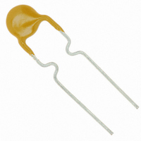
... Patents pending MF-R Series - PTC Resettable Fuses Product Dimensions (see next page for outline drawing Model Max. Max. 8.0 8.3 MF-R005 (0.315) (0.327) 7.4 12.7 MF-R010 (0.291) (0.5) 7.4 12.7 MF-R017 (0.291) (0.5) 7.4 12.7 MF-R020 (0.291) (0.5) 7.4 12.7 MF-R025 (0 ...

Page 3

... NOTE: Kinked lead option is available for board standoff. Contact factory for details. Thermal Derating Chart - I hold / I trip (Amps) Model -40 ºC -20 ºC MF-R005 0.08 / 0.16 0.07 / 0.14 MF-R010 0.16 / 0.32 0.14 / 0.28 MF-R017 0.26 / 0.52 0.23 / 0.46 MF-R020 0.31 / 0.62 0.27 / 0.54 MF-R025 ...

Page 4

... Fault Current (Amps) 10 100 10 100 Customers should verify actual device performance in their specifi c applications. How to Order 110 - Multifuse ® Product Designator Series R = Radial Leaded Component Hold Current, I hold 005-1100 (0.05 Amps - 11.0 Amps) Packaging Options - __ = Bulk Packaging without part number suffi ...

Page 5

... Device pitch: MF-R005–MF-R160, MF-R/90, MF-RX110/72–MF-RX185/72 Device pitch: MF-R185–MF-R400, MF-RX110–MF-RX375 MF-R/600, MF-RX250/72–MF-RX375/72 Tape thickness Tape thickness with splice: MF-R010–MF-R160, MF-RX110/72–MF-RX185/72 Tape thickness with splice: MF-R250–MF-R1100, MF-RX110–MF-RX375, MF-R/90, MF-RX250/72-MF-RX375/72 Splice sprocket hole alignment Body lateral deviation Body tape plane deviation Specifi ...

Page 6

... MF-R, MF-R/90, MF-R/600, MF-RX, MF-RX/72 & MF-RX/250 Series Tape and Reel Specifi cations Dimension Description Lead spacing: MF-R, MF-R/90, MF-R/600, MF-RX, MF-RX/72 Lead spacing: MF-RX/250 Reel width Reel diameter Space between fl anges less device Arbor hole diameter Core diameter: MF-R, MF-RX, MF-R/90 ...

Related keywords