*** UL approved, TÜV pending.
****Agency approval pending.
Operating Temperature ......................................... -40 °C to +85 °C
Maximum Device Surface Temperature
Passive Aging ....................................................... +85 °C, 1000 hours ............................................... ±5 % typical resistance change
Humidity Aging ..................................................... +85 °C, 85 % R.H. 1000 hours ............................. ±5 % typical resistance change
Thermal Shock ..................................................... +85 °C to -40 °C, 20 times ................................... ±10 % typical resistance change
Solvent Resistance ............................................... MIL-STD-202, Method 215 ................................... No change
Vibration ............................................................... MIL-STD-883C, Method 2007.1, .......................... No change
.............................................................................. Condition A
Test
Visual/Mech. ......................................................... Verify dimensions and materials ........................... Per MF physical description
Resistance ............................................................ In still air @ 23 °C .................................................. Rmin ≤ R ≤ R1max
Time to Trip ........................................................... At specifi ed current, Vmax, 23 °C ........................ T ≤ max. time to trip (seconds)
Hold Current ......................................................... 30 min. at Ihold ..................................................... No trip
Trip Cycle Life ....................................................... Vmax, Imax, 100 cycles ........................................ No arcing or burning
Trip Endurance ..................................................... Vmax, 48 hours ..................................................... No arcing or burning
Solderability .......................................................... ANSI/J-STD-002 ................................................... 95 % min. coverage
UL File Number .................................................... E174545
CSA File Number .................................................. CA110338
TÜV Certifi cate Number ....................................... R 02057213
MF-SMDF050
MF-SMDF150***
MF-SMDF200****
Environmental Characteristics
Test Procedures And Requirements For Model MF-SMDF Series
MF-SMDF050
MF-SMDF150
MF-SMDF200
in Tripped State ................................................. 125 °C
Thermal Derating Chart - I hold /I trip (Amps)
Electrical Characteristics
Model
Model
0.87 / 1.90
2.38 / 4.76
2.95 / 5.90
-40 °C
V max.
Volts
60
15
10
0.77 / 1.68
2.10 / 4.20
2.65 / 5.30
**To be considered halogen free, each homogenous material can have a maximum concentration of 900 ppm of either bromine or chlorine.
-20 °C
I max.
Amps
10
40
40
0.67 / 1.46
1.82 / 3.64
2.35 / 4.70
I hold
Hold
Test Conditions
http://www.ul.com/ Follow link to Certifi cations, then UL File No., enter E174545
http://directories.csa-international.org/ Under “Certifi cation Record” and “File Number”
enter 110338-0-000
http://www.tuvdotcom.com/ Follow link to “other certifi cates”, enter File No. 2057213
Features
■
■
■
■
■
■
■
0.55
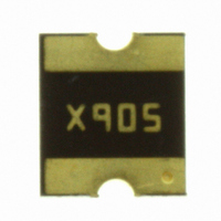
MF-SMDF Series - PTC Resettable Fuses
1.5
2.0
0 °C
Very low profi le
Very fast tripping time
High voltage
RoHS compliant* and halogen free**
Symmetrical
2018 footprint
Agency recognition:
Amperes
at 23 °C
0.55 / 1.20
1.50 / 3.00
2.00 / 4.00
I trip
1.20
3.00
4.00
Ambient Operating Temperature
Trip
23 °C
0.46 / 1.00
1.27 / 2.54
1.74 / 3.48
R Min.
0.200
0.05
0.03
40 °C
Resistance
Customers should verify actual device performance in their specifi c applications.
at 23 °C
Ohms
R 1Max.
0.41 / 0.89
1.13 / 2.26
1.59 / 3.18
0.100
0.17
1.0
50 °C
*RoHS Directive 2002/95/EC Jan 27 2003 including Annex.
Applications
■
■
■
Accept/Reject Criteria
Power Over Ethernet (IEEE 802.3 af) port
protection
Automotive electronic control module
protection
Telecom equipment low voltage
protection
Amperes
at 23 °C
0.36 / 0.79
0.99 / 1.98
1.44 / 2.88
Specifi cations are subject to change without notice.
2.5
8.0
8.0
60 °C
Max. Time
To Trip
Seconds
at 23 °C
0.31 / 0.68
0.85 / 1.70
1.29 / 2.58
2.40
3.0
0.8
70 °C
Dissipation
at 23 °C
Tripped
0.23 / 0.50
0.64 / 1.28
1.06 / 2.12
Power
Watts
Typ.
0.9
1.1
1.1
85 °C


