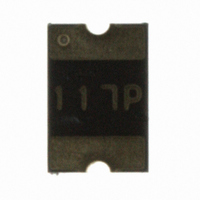
MF-MSMF110-2 Bourns Inc., MF-MSMF110-2 Datasheet - Page 3

MF-MSMF110-2
Manufacturer Part Number
MF-MSMF110-2
Description
PTC RESETTABLE 1.10A 6V 1812
Manufacturer
Bourns Inc.
Series
MF-MSMFr
Type
PTC Resettable Fusesr
Datasheet
1.MF-MSMF110-2.pdf
(5 pages)
Specifications of MF-MSMF110-2
Package / Case
1812 (4532 Metric)
R Min/max
0.040 ~ 0.210 Ohm
Voltage - Max
6V
Time To Trip
0.3s
Current - Hold (ih) (max)
1.1A
Current - Trip (it)
2.2A
Current - Max
100A
Hold Current
1.1 Amps
Trip Current
2.2 Amps
Current Rating (max)
100 Amps
Resistance
0.21 Ohms
Maximum Voltage
6 VoltsDC
Termination Style
SMD/SMT
Mounting Style
SMD/SMT
Current Rating
100 Amps
Dimensions
4.73 mm L x 3.41 mm W x 0.75 mm H
Operating Temperature Range
- 40 C to + 85 C
Holding Current
1.1A
Tripping Current
2.2A
Initial Resistance Max
0.21ohm
Operating Voltage
6V
Ptc Fuse Case
1812
External Depth
0.50mm
Initial Resistance Min
0.04ohm
Rohs Compliant
Yes
Lead Free Status / RoHS Status
Lead free / RoHS Compliant
Lead Free Status / RoHS Status
Lead free / RoHS Compliant, Lead free / RoHS Compliant
Other names
MF-MSMF110-2TR
Available stocks
Company
Part Number
Manufacturer
Quantity
Price
Company:
Part Number:
MF-MSMF110-2
Manufacturer:
BOURNS
Quantity:
60 000
Part Number:
MF-MSMF110-2
Manufacturer:
BOURNS/伯恩斯
Quantity:
20 000
Specifi cations are subject to change without notice.
Customers should verify actual device performance in their specifi c applications.
Style 1
Style 2
Product Dimensions (see previous page for dimensions)
Typical Time to Trip at 23 ˚C
Top and Bottom View
MF-MSMF Series - PTC Resettable Fuses
Top View
MF-MSMF010
0.001
8
C
0.01
A
100
0.1
10
1
0.1
MF-MSMF030
D
B
D
Side View
C
Bottom View
A
1
Fault Current (Amps)
Recommended Pad Layout
(.059 ± .002)
1.5 ± 0.05
MF-MSMF014
(.106 ± .004)
B
2.7 ± 0.1
MF-MSMF020
MF-MSMF075/24
Side View
MF-MSMF050
(.066 ± .002)
1.68 ± 0.05
MF-MSMF200
C
10
(0.126 ± .004)
Recommended Pad Layout
MF-MSMF260
3.2 ± 0.1
(.059 ± .002)
1.5 ± 0.05
MF-MSMF160
MF-MSMF110
MF-MSMF075
MF-MSMF150
MF-MSMF110/16
MF-MSMF125
100
(.122 ± .004)
3.1 ± 0.10
(.114 ± .004)
2.95 ± 0.10
Terminal material:
Termination pad solderability:
Recommended Storage:
The Time to Trip curves represent typical
performance of a device in a simulated
application environment. Actual performance
in specifi c customer applications may differ
from these values due to the infl uence of
other variables.
Electroless Ni under immersion Au
Standard Au fi nish:
Meets ANSI/J-STD-002 Category 2.
40 °C max./70 % RH max.


