CL-90A GE Sensing, CL-90A Datasheet - Page 2
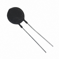
CL-90A
Manufacturer Part Number
CL-90A
Description
NTC THERM CURR LIMIT INRUSH
Manufacturer
GE Sensing
Series
CLr
Type
NTCr
Datasheet
1.CL-90A.pdf
(4 pages)
Specifications of CL-90A
R @ 25°c
120 Ohm
R @ Current
1.18 Ohm
Current - Steady State Max
2A
Tolerance
±25%
Diameter
0.93" (23.62mm)
Lead Spacing
0.328" (8.33mm)
Resistance
120 Ohms
Termination Style
Radial
Operating Temperature Range
- 50 C to + 175 C
Current Rating
2 Amps
Voltage
120 V
Lead Free Status / RoHS Status
Lead free / RoHS Compliant
Other names
AB15190
CL-90-A
CL-90-A
Q2025121
Q2320551
CL-90-A
CL-90-A
Q2025121
Q2320551


Sensing
Type CL
Specifications
NTC discs for inrush current limiting
Description
Disc thermistor with uninsulated lead-wires.
Type
Fig. 1
CL-11
CL-21
CL-30
CL-40
CL-50
CL-60
CL-70
CL-80
CL-90
CL-101
CL-110
CL-120
CL-130
CL-140
CL-150
CL-160
CL-170
CL-180
CL-190
CL-200
CL-210
Res
@ 77°F Steady
(25°C)
±25%
(Ω Ω )
0.7
1.3
2.5
5
7
10
16
47
120
0.5
10
10
50
50
5
5
16
16
25
25
30
Max*
State
Current
AMPS
(RMS)
12
8
8
6
5
5
4
3
2
16
3.2
1.7
1.6
1.1
4.7
2.8
2.7
1.7
2.4
1.7
1.5
Disc
Dia.
(Max)
(mm)
0.77
(19.55)
0.55
(13.97)
0.77
(19.55)
0.77
(19.55)
0.77
(19.55)
0.77
(19.55)
0.77
(19.55)
0.77
(19.55)
0.93
(23.62)
0.93
(23.62)
0.40
(10.16)
0.40
(10.16)
0.45
(11.45)
0.45
(11.45)
0.55
(13.97)
0.55
(13.97)
0.55
(13.97)
0.55
(13.97)
0.55
(13.97)
0.55
(13.97)
0.40
(10.16)
in
Disc
Thick.
(Max)
in
(mm)
0.22
(5.58)
0.21
(5.334)
0.22
(5.58)
0.22
(5.58)
0.26
(6.60)
0.22
(5.58)
0.22
(5.58)
0.22
(5.58)
0.22
(5.58)
0.22
(5.58)
0.17
(4.31)
0.17
(4.31)
0.17
(4.31)
0.17
(4.31)
0.18
(4.57)
0.18
(4.57)
0.18
(4.57)
0.18
(4.57)
0.18
(4.57)
0.18
(4.57)
0.20
(5.08)
Lead
Spacing Dia.
(Ref.)
in
(mm)
0.328
(8.33)
0.328
(8.33)
0.328
(8.33)
0.328
(8.33)
0.328
(8.33)
0.328
(8.33)
0.328
(8.33)
0.328
(8.33)
0.328
(8.33)
0.328
(8.33)
0.250
(6.35)
0.250
(6.35)
0.250
(6.35)
0.250
(6.35)
0.328
(8.33)
0.328
(8.33)
0.328
(8.33)
0.328
(8.33)
0.328
(8.33)
0.328
(8.33)
0.250
(6.35)
Lead
AWG
18
18
18
18
18
18
18
18
18
18
24
24
24
24
22
22
22
22
22
22
24
C
µ µ Farads
@120
VAC
2700
800
6000
5200
5000
5000
5000
5000
5000
4000
600
600
600
600
1600
1600
1600
1600
800
800
600
x
(max)**
@240
VAC
600
200
1500
1300
1250
1250
1250
1250
1250
1000
150
150
150
150
400
400
400
400
200
200
150
Equation constants for
resistance under load ***
X
0.50
0.60
0.81
1.09
1.28
1.45
1.55
2.03
3.04
0.44
0.83
0.61
1.45
1.01
0.81
0.60
1.18
0.92
1.33
0.95
1.02
Options
• For kinked leads, add suffix “A”
• For tape and reel, add suffix “B”
• Other tolerances in the range 0.7 Ω to 120 Ω
• Other tolerances, tolerances at other temperatures
• Alternative lead lengths, lead materials, insulations
Data
*maximum rating at 77°F (25ºC) or
I
ambient temperatures other than 77°F (25ºC).
**maximum ratings
***R
derated
Y
-1.18
-1.25
-1.25
-1.27
-1.27
-1.30
-1.26
-1.29
-1.36
-1.12
-1.29
-1.09
-1.38
-1.28
-1.26
-1.05
-1.28
-1.18
-1.34
-1.24
-1.35
0
=X1
= √(1.1425–0.0057 x T
Current
Range
Min. I / Max. I
4.0≤ 1≤12
3.0≤ 1≤ 8.0
2.5≤ 1≤ 8.0
1.5≤ 1≤ 6.0
1.5≤ 1≤ 5.0
1.2≤ 1≤ 5.0
1.0≤ 1≤ 4.0
0.5≤ 1≤ 3.0
0.5≤ 1≤ 2.0
4.0≤ 1≤ 16
0.7≤ 1≤ 3.2
0.4≤ 1≤ 1.7
0.4≤ 1≤ 1.6
0.2≤ 1≤ 1.1
1.0≤ 1≤ 4.7
0.8≤ 1≤ 2.8
0.5≤ 1≤ 2.7
0.4≤ 1≤ 1.7
0.5≤ 1≤ 2.4
0.4≤ 1≤ 1.7
0.3≤ 1≤ 1.5
Y
where X and Y are found in the table below
Approx. Res. Under Load at %
Maximum Rated Current
25%
14
0.25
0.34
0.65
0.96
1.09
1.55
2.94
7.80
0.09
1.10
1.55
5.13
5.27
0.66
0.87
1.95
2.52
2.63
2.74
3.83
50%
0.06
0.09
0.14
0.27
0.40
0.44
0.65
1.20
3.04
0.04
0.45
0.73
1.97
2.17
0.27
0.42
0.80
1.11
1.04
1.18
1.50
A
) x I
75%
0.04
0.06
0.09
0.16
0.24
0.26
0.39
0.71
1.75
0.03
0.27
0.46
1.13
1.28
0.16
0.27
0.48
0.69
0.60
0.70
0.87
max
@ 77°F (25°C) for
100%
0.02
0.04
0.06
0.11
0.16
0.18
0.27
0.49
1.18
0.02
0.18
0.34
0.75
0.89
0.11
0.20
0.33
0.49
0.41
0.49
0.60
Diss.
Const.
(mW/°C) (sec.)
25
15
25
25
25
25
25
25
30
30
8
4
8
4
15
9
15
9
15
9
8
Time
Const.
100
60
100
100
120
100
100
100
120
120
30
90
30
90
110
130
110
130
110
130
30
Related parts for CL-90A
Image
Part Number
Description
Manufacturer
Datasheet
Request
R

Part Number:
Description:
CURRENT LIMITER INRUSH
Manufacturer:
GE Sensing
Datasheet:

Part Number:
Description:
CURRENT LIMITER INRUSH
Manufacturer:
GE Sensing
Datasheet:
Part Number:
Description:
CURRENT LIMITER INRUSH
Manufacturer:
GE Sensing
Datasheet:
Part Number:
Description:
CURRENT LIMITER INRUSH
Manufacturer:
GE Sensing
Datasheet:

Part Number:
Description:
CURRENT LIMITER INRUSH
Manufacturer:
GE Sensing
Datasheet:
Part Number:
Description:
CURRENT LIMITER INRSH 2.8A 5 OHM
Manufacturer:
GE Sensing
Datasheet:
Part Number:
Description:
CURRENT LIMITER INRUSH
Manufacturer:
GE Sensing
Datasheet:

Part Number:
Description:
CURRENT LIMITER INRUSH
Manufacturer:
GE Sensing
Datasheet:
Part Number:
Description:
CURRENT LIMITER INRUSH
Manufacturer:
GE Sensing
Datasheet:
Part Number:
Description:
CURRENT LIMITER INRUSH
Manufacturer:
GE Sensing
Datasheet:

Part Number:
Description:
IC, SENSOR, SMD, 1PSI, MV O/P, DIFF
Manufacturer:
GE Sensing
Datasheet:
Part Number:
Description:
IC, SENSOR, SMD, 5PSI, MV O/P, DIFF
Manufacturer:
GE Sensing
Datasheet:
Part Number:
Description:
SENSOR, SMD, 10INH20, MV O/P, DIFF
Manufacturer:
GE Sensing
Datasheet:
Part Number:
Description:
SENSOR, SMD, 15PSI, MV O/P, ABSOLUTE
Manufacturer:
GE Sensing
Datasheet:
Part Number:
Description:
SENSOR, SMD, 15PSI, MV O/P, DIFF
Manufacturer:
GE Sensing
Datasheet: