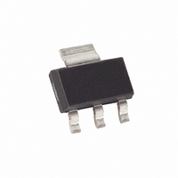
DS1233Z-15 Maxim Integrated Products, DS1233Z-15 Datasheet - Page 2

DS1233Z-15
Manufacturer Part Number
DS1233Z-15
Description
IC ECONORESET 5V 15% SOT-223-3
Manufacturer
Maxim Integrated Products
Series
EconoResetr
Type
Simple Reset/Power-On Resetr
Datasheet
1.DS1233-15.pdf
(5 pages)
Specifications of DS1233Z-15
Number Of Voltages Monitored
1
Output
Open Drain or Open Collector
Reset
Active Low
Reset Timeout
250 ms Minimum
Voltage - Threshold
4.125V
Operating Temperature
-40°C ~ 85°C
Mounting Type
Surface Mount
Package / Case
SOT-223 (3 leads + Tab), SC-73, TO-261
Monitored Voltage
5 V
Undervoltage Threshold
4 V
Overvoltage Threshold
4.24 V
Output Type
Active Low, Open Drain
Manual Reset
Resettable
Watchdog
No Watchdog
Battery Backup Switching
No Backup
Power-up Reset Delay (typ)
450 ms
Supply Voltage (max)
5.5 V
Supply Voltage (min)
1.2 V
Supply Current (typ)
50 uA
Maximum Operating Temperature
+ 85 C
Mounting Style
SMD/SMT
Minimum Operating Temperature
- 40 C
Power Fail Detection
Yes
Lead Free Status / RoHS Status
Contains lead / RoHS non-compliant
Other names
DS1233Z15
Available stocks
Company
Part Number
Manufacturer
Quantity
Price
Company:
Part Number:
DS1233Z-15+
Manufacturer:
Maxim
Quantity:
1 167
DS1233
OPERATION — PUSHBUTTON RESET
The DS1233 provides for a pushbutton switch to be connected to the
output pin. When the DS1233
RST
is not in a reset cycle, it continuously monitors the
signal for a low going edge. If an edge is
RST
detected, the DS1233 will debounce the switch by pulling the
line low. After the internal timer has
RST
expired, the DS1233 will continue to monitor the
line. If the line is still low, the DS1233 will
RST
continue to monitor the line looking for a rising edge. Upon detecting a release, the DS1233 will force the
line low and hold it low for 350ms.
RST
NOTE:
For proper operation with an external pushbutton, a capacitor between 100pF and 0.01mF must be
connected between
and ground. In applications where additional reset current is required, a
RST
minimum capacitance of 500pF should be used, along with a parallel external pull-up resistor of
1kW minimum.
BLOCK DIAGRAM Figure 1
APPLICATION EXAMPLE Figure 2
2 of 5


