DS1813-10/T&R Maxim Integrated Products, DS1813-10/T&R Datasheet
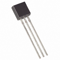
IC ECONORESET 5V W/PB 10% TO92-3

DS1813-10/T&R

Manufacturer Part Number
DS1813-10/T&R
Description
IC ECONORESET 5V W/PB 10% TO92-3
Manufacturer
Maxim Integrated Products
Series
EconoResetr
Type
Simple Reset/Power-On Resetr
Datasheet

Specifications of DS1813-10/T&R

Number Of Voltages Monitored
1
Output
Open Drain or Open Collector
Reset
Active Low
Reset Timeout
100 ms Minimum
Voltage - Threshold
4.35V
Operating Temperature
-40°C ~ 85°C
Mounting Type
Through Hole
Package / Case
TO-92-3 (Standard Body), TO-226
Lead Free Status / RoHS Status
Contains lead / RoHS non-compliant
www.maxim-ic.com
GENERAL DESCRIPTION
The DS1813 EconoReset uses a precision
temperature reference and comparator circuit to
monitor the status of the power supply (V
When an out-of-tolerance condition is detected,
an internal power-fail signal is generated which
forces reset to the active state. When V
to an in-tolerance condition, the reset signal is
kept in the active state for approximately 150ms
to allow the power supply and processor to
stabilize.
The DS1813 also monitors a pushbutton on the
reset output. If the reset line is pulled low, a reset
is generated upon release and will be held in reset
output low for typically 150ms.
FEATURES
Automatically Restarts a Microprocessor
After Power Failure
Monitors Pushbutton for External Override
Maintains Reset for Typically 150ms After
V
Reduces Need for Discrete Components
Precision Temperature-Compensated Voltage
Reference and Voltage Sensor
Low-Cost TO-92 or Space-Saving Surface-
Mount SOT-23 Packages Available
Efficient Open-Drain Output with Internal
5.5kΩ Pullup Resistor
-40°C to +85°C Operating Temperature
CC
Returns to an In-Tolerance Condition
CC
returns
CC
5V EconoReset with Pushbutton
).
1 of 5
PIN CONFIGURATIONS
PIN DESCRIPTION
TO-92
1
2
3
PIN
TO-92 PACKAGE
Drawings Section
BOTTOM VIEW
SOT-23
On Website
See Mech.
1 2 3
1 2 3
DALLAS
DS1813
Econo
Reset
1
2
3
NAME
GND
RST
V
CC
SOT-23 PACKAGE
Drawings Section
1
TOP VIEW
On Website
See Mech.
Active-Low
Reset Output
Power Supply
Ground
3
FUNCTION
DS1813
2
REV: 022306

Related parts for DS1813-10/T&R

DS1813-10/T&R Summary of contents

Page 1

... The DS1813 also monitors a pushbutton on the reset output. If the reset line is pulled low, a reset is generated upon release and will be held in reset output low for typically 150ms. ...

Page 2

... OPERATION—PUSHBUTTON RESET The DS1813 provides for a pushbutton switch for manual reset control. When the DS1813 is not in a reset cycle, a pushbutton reset can be generated by pulling the RST pin low for at least 1µs. When the pushbutton is held low, the RST is forced active low and will remain active low for about 150ms after the pushbutton is released ...

Page 3

Figure 3. Timing Diagram: Pushbutton Reset Figure 4. Timing Diagram: Power-Up Figure 5. Timing Diagram: Power-Down ...

Page 4

... CC A PARAMETER Output Current at 0.4V Voltage Input Low Voltage Input High Operating Current V < 5.5 CC DS1813-5 V Trip Point DS1813-10 CC DS1813-15 Internal Pullup Resistor Output Capacitance AC ELECTRICAL CHARACTERISTICS (V = 1.2V to 5.5V -40°C to +85°C PARAMETER Reset Active Time V Detect to RST CC V ...

Page 5

... PART MARKING CODES “A,” “B,” and “C” represent the device type. 810 . . . . DS1810 811 . . . . DS1811 812 . . . . DS1812 813 . . . . DS1813 815 . . . . DS1815 816 . . . . DS1816 817 . . . . DS1817 818 . . . . DS1818 Maxim/Dallas Semiconductor cannot assume responsibility for use of any circuitry other than circuitry entirely embodied in a Maxim/Dallas Semiconductor product. ...

Related keywords