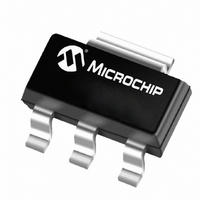
TC32MCDB Microchip Technology, TC32MCDB Datasheet - Page 5

TC32MCDB
Manufacturer Part Number
TC32MCDB
Description
IC SYSTEM SUPERVISOR SOT223-3
Manufacturer
Microchip Technology
Series
ECONOMONITOR™r
Type
Simple Reset/Power-On Resetr
Datasheet
1.TC32MEDB713.pdf
(12 pages)
Specifications of TC32MCDB
Number Of Voltages Monitored
1
Output
Open Drain or Open Collector
Reset
Active Low
Reset Timeout
500 ms Minimum
Voltage - Threshold
4.375V
Operating Temperature
0°C ~ 70°C
Mounting Type
Surface Mount
Package / Case
SOT-223 (3 leads + Tab), SC-73, TO-261
Manual Reset
Not Resettable
Watchdog
Watchdog
Battery Backup Switching
No Backup
Supply Voltage (max)
5.5 V
Supply Voltage (min)
4.5 V
Supply Current (typ)
200 uA
Maximum Operating Temperature
+ 70 C
Mounting Style
SMD/SMT
Minimum Operating Temperature
0 C
Power Fail Detection
No
Undervoltage Threshold
4.25 V
Overvoltage Threshold
4.5 V
Output Type
Open Drain
Power-up Reset Delay (typ)
900 ms
Lead Free Status / RoHS Status
Lead free / RoHS Compliant
Available stocks
Company
Part Number
Manufacturer
Quantity
Price
Company:
Part Number:
TC32MCDB
Manufacturer:
MICROCHIP
Quantity:
12 000
Company:
Part Number:
TC32MCDB713
Manufacturer:
MICROCHIP
Quantity:
12 000
3.0
The TC32M provides three important functions to
safeguard stable processor operation: precision pro-
cessor monitor, Watchdog sanity timer and external
override Reset control.
3.1
The RS pin is immediately driven low any time V
below the nominal threshold voltage. As a result, this
pin is LOW when power is initially applied, holding the
processor in its Reset state. RS remains low for a
minimum of 500 msec after V
allow the power supply and processor to stabilize.
3.2
The processor drives the RS pin with an input/output
(I/O) line in series with an resistor voltage divider to
V
results in an internal voltage change (strobe) sufficient
to reset the Watchdog Timer, but above the V
threshold of the processor Reset pin. The processor
must continuously apply strobes in this manner within
a set period to verify proper software execution. A
momentary Reset (500 msec minimum) is generated
by the TC32M if a hardware or software failure keeps
RS from being strobed within the Watchdog Time-out
period. This action typically initiates the processor’s
power-up routine. If the interruption persists, new
Reset pulses are generated each time-out period until
RS is strobed. This time-out period is typically 700
msec.
© 2006 Microchip Technology Inc.
DD.
Pulling the bottom resistor of this divider low
DETAILED DESCRIPTION
Processor Monitor
Watchdog Timer
DD
is within tolerance to
IL
DD
input
is
FIGURE 3-1:
The software routine that drives the RS strobe must be
in a section of the program that executes frequently
enough so the time between toggles is less than one
Watchdog Time-out period. The strobe signal can be
derived from microprocessor address, data and/or
control signals. Typical circuit examples are shown in
Figure .
3.3
The values of R1 and R2 must be chosen to ensure a
valid low strobe level (V
I/O line is low. The use of 10 kΩ, ±5% tolerance
resistors are recommended. These values result in a
nominal strobe level of 2.5 on RS (min/max of 2.13V/
3.08V, assuming V
values can be used, so long as the additive tolerances
of the power supply and resistor values result in a
strobe that falls within V
tolerance conditions.
Note: t
will keep the watchdog timer from forcing RS LOW.
(A Strobe is defined as a high-to-low transition from V
V
V
V
STH
ST
STL
L (Max)
(Min)
(Min)
TD
RS
is the maximum elapsed time between strobes which
Resistor Value Selection
t
DD
ST
Watchdog Strobe
STL
= 5.0V ±10%). Other resistor
STH
) on RS when the processor
t
and V
TD
STL
TC32M
under all additive
DS21402C-page 5
STH
to V
STL
).


