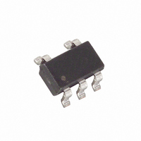
MAX6414UK46+T Maxim Integrated Products, MAX6414UK46+T Datasheet - Page 9

MAX6414UK46+T
Manufacturer Part Number
MAX6414UK46+T
Description
IC RESET MPU LOW PWR SOT23-5
Manufacturer
Maxim Integrated Products
Type
Simple Reset/Power-On Resetr
Datasheet
1.MAX6417UKT.pdf
(12 pages)
Specifications of MAX6414UK46+T
Number Of Voltages Monitored
1
Output
Open Drain or Open Collector
Reset
Active Low
Reset Timeout
Adjustable/Selectable
Voltage - Threshold
4.625V
Operating Temperature
-40°C ~ 125°C
Mounting Type
Surface Mount
Package / Case
SOT-23-5, SC-74A, SOT-25
Monitored Voltage
1.6 V to 5 V
Undervoltage Threshold
4.509 V
Overvoltage Threshold
4.741 V
Output Type
Active Low, Open Drain
Manual Reset
Resettable
Watchdog
No Watchdog
Battery Backup Switching
No Backup
Power-up Reset Delay (typ)
5.4 ms
Supply Voltage (max)
5.5 V
Supply Voltage (min)
1 V
Supply Current (typ)
2.7 uA
Maximum Power Dissipation
571 mW
Maximum Operating Temperature
+ 125 C
Mounting Style
SMD/SMT
Minimum Operating Temperature
- 40 C
Power Fail Detection
No
Lead Free Status / RoHS Status
Lead free / RoHS Compliant
Other names
MAX6414UK46+T
MAX6414UK46+TTR
MAX6414UK46+TTR
SRT is a precise current source. When developing the
layout for the application, be careful to minimize board
capacitance and leakage currents around this pin.
Traces connected to SRT should be kept as short as
possible. Traces carrying high-speed digital signals
and traces with large voltage potentials should be rout-
ed as far from SRT as possible. Leakage current and
stray capacitance (e.g., a scope probe) at this pin
could cause errors in the reset timeout period. When
evaluating these parts, use clean prototype boards to
ensure accurate reset periods.
RESET IN is a high-impedance input, which is typically
driven by a high-impedance resistor-divider network
(e.g., 1MΩ to 10MΩ). Minimize coupling to transient sig-
nals by keeping the connections to this input short. Any
DC leakage current at RESET IN (e.g., a scope probe)
causes errors in the programmed reset threshold.
TRANSISTOR COUNT: 325
PROCESS: BiCMOS
Low-Power, Single/Dual-Voltage µP Reset Circuits
with Capacitor-Adjustable Reset Timeout Delay
_______________________________________________________________________________________
Layout Consideration
Chip Information
Table 1. Reset Voltages Suffix Table
SUFFIX
16
17
18
19
20
21
22
23
24
25
26
27
28
29
30
31
32
33
34
35
36
37
38
39
40
41
42
43
44
45
46
47
48
49
50
1.536
1.623
1.755
1.853
1.950
2.048
2.133
2.313
2.340
2.438
2.559
2.633
2.730
2.852
2.925
2.998
3.120
3.218
3.315
3.413
3.510
3.608
3.705
3.803
3.900
3.998
4.095
4.193
4.266
4.388
4.509
4.583
4.680
4.778
4.875
MIN
1.575
1.665
1.800
1.900
2.000
2.100
2.188
2.313
2.400
2.500
2.625
2.700
2.800
2.925
3.000
3.075
3.200
3.300
3.400
3.500
3.600
3.700
3.800
3.900
4.000
4.100
4.200
4.300
4.375
4.500
4.625
4.700
4.800
4.900
5.000
TYP
1.614
1.707
1.845
1.948
2.050
2.153
2.243
2.371
2.460
2.563
2.691
2.768
2.870
2.998
3.075
3.152
3.280
3.383
3.485
3.558
3.690
3.793
3.895
3.998
4.100
4.203
4.305
4.408
4.484
4.613
4.741
4.818
4.920
5.023
5.125
MAX
9


