NCS2001SQ2T2 ON Semiconductor, NCS2001SQ2T2 Datasheet - Page 2
NCS2001SQ2T2
Manufacturer Part Number
NCS2001SQ2T2
Description
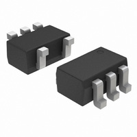
IC OPAMP R-R 0.9V 1MHZ SOT-353
Manufacturer
ON Semiconductor
Datasheet
1.NCS2001SN1T1G.pdf
(17 pages)
Specifications of NCS2001SQ2T2
Amplifier Type
General Purpose
Number Of Circuits
1
Output Type
Rail-to-Rail
Slew Rate
1.6 V/µs
Gain Bandwidth Product
1.4MHz
Current - Input Bias
10pA
Voltage - Input Offset
500µV
Current - Supply
820µA
Current - Output / Channel
96mA
Voltage - Supply, Single/dual (±)
0.9 V ~ 7 V, ±0.45 V ~ 3.5 V
Operating Temperature
-40°C ~ 105°C
Mounting Type
Surface Mount
Package / Case
SC-70-5, SC-88A, SOT-323-5, SOT-353, 5-TSSOP
Lead Free Status / RoHS Status
Contains lead / RoHS non-compliant
-3db Bandwidth
-
Available stocks
Company
Part Number
Manufacturer
Quantity
Price

Part Number:
NCS2001SQ2T2G
Manufacturer:
ON/安森美
Quantity:
20 000


Stresses exceeding Maximum Ratings may damage the device. Maximum Ratings are stress ratings only. Functional operation above the
Recommended Operating Conditions is not implied. Extended exposure to stresses above the Recommended Operating Conditions may affect
device reliability.
1. Either or both inputs should not exceed the range of V
2. Maximum package power dissipation limits must be observed to ensure that the maximum junction temperature is not exceeded.
3. NCV prefix is qualified for automotive usage.
4. ESD data available upon request.
MAXIMUM RATINGS
DC ELECTRICAL CHARACTERISTICS
(V
Supply Voltage (V
Input Differential Voltage Range (Note 1)
Input Common Mode Voltage Range (Note 1)
Output Short Circuit Duration (Note 2)
Junction Temperature
Power Dissipation and Thermal Characteristics
Operating Ambient Temperature Range
Storage Temperature Range
ESD Protection at any Pin Human Body Model (Note 4)
Input Offset Voltage
Input Offset Voltage Temperature Coefficient (R
Input Bias Current (V
Input Common Mode Voltage Range
Large Signal Voltage Gain
SOT23−5 Package
SC70−5 Package
NCS2001
NCV2001 (Note 3)
CC
V
V
V
T
V
V
V
J
CC
CC
CC
Thermal Resistance, Junction−to−Air
Power Dissipation @ T
Thermal Resistance, Junction−to−Air
Power Dissipation @ T
CC
CC
CC
= T
= 2.5 V, V
T
T
T
T
T
T
T
T
T
T
R
R
R
R
R
R
A
A
A
A
A
A
A
A
A
A
= 0.45 V, V
= 1.5 V, V
= 2.5 V, V
L
L
L
L
L
L
= 0.45 V, V
= 1.5 V, V
= 2.5 V, V
A
= 25°C
= 0°C to 70°C
= −40°C to 125°C
= 25°C
= 0°C to 70°C
= −40°C to 125°C
= 25°C
= 0°C to 70°C
= −40°C to 125°C
= −40°C to 125°C
= 10 k
= 2.0 k
= 10 k
= 2.0 k
= 10 k
= 2.0 k
+ (P
D
EE
R
EE
EE
qJA
EE
EE
EE
= −2.5 V, V
CC
EE
= −1.5 V
= −2.5 V
).
= −1.5 V
= −2.5 V
= −0.45 V
CC
to V
= −0.45 V
Characteristics
= 1.0 V to 5.0 V)
EE
A
A
)
= 70°C
= 70°C
CM
= V
O
Rating
= 0 V, R
L
to GND, T
S
= 50)
EE
http://onsemi.com
A
−300 mV to V
= 25°C unless otherwise noted.)
2
DV
Symbol
EE
A
V
V
IO
I
VOL
ICR
IB
IO
+7.0 V.
/DT
Symbol
V
V
V
R
R
−6.0
−8.5
−9.5
−6.0
−7.0
−7.5
−6.0
−7.5
−7.5
Min
T
V
t
P
P
T
T
20
15
ESD
IDR
ICR
Sc
qJA
qJA
stg
−
−
−
−
−
−
−
A
S
D
D
J
V
V
V
EE
EE
EE
Typ
0.5
0.5
0.5
8.0
10
40
20
40
40
40
40
to V
−300 mV to 7.0 V
−300 mV to 7.0 V
−
−
−
−
−
−
−40 to +105
−40 to +125
−65 to 150
Indefinite
Value
CC
2000
150
235
340
280
286
7.0
Max
6.0
8.5
9.5
6.0
7.0
7.5
6.0
7.5
7.5
−
−
−
−
−
−
−
−
−
°C/W
°C/W
Unit
mW
mW
mV/°C
sec
kV/V
Unit
°C
°C
°C
mV
V
V
V
V
pA
V
Related parts for NCS2001SQ2T2
Image
Part Number
Description
Manufacturer
Datasheet
Request
R

Part Number:
Description:
0.9 V, Rail-to-rail, Single Operational Amplifier
Manufacturer:
ON Semiconductor
Datasheet:
Part Number:
Description:
ON Semiconductor [VOLTAGE REGULATOR]
Manufacturer:
ON Semiconductor
Datasheet:
Part Number:
Description:
357-036-542-201 CARDEDGE 36POS DL .156 BLK LOPRO
Manufacturer:
ON Semiconductor
Datasheet:
Part Number:
Description:
357-036-542-201 CARDEDGE 36POS DL .156 BLK LOPRO
Manufacturer:
ON Semiconductor
Datasheet:
Part Number:
Description:
357-036-542-201 CARDEDGE 36POS DL .156 BLK LOPRO
Manufacturer:
ON Semiconductor
Datasheet:
Part Number:
Description:
357-036-542-201 CARDEDGE 36POS DL .156 BLK LOPRO
Manufacturer:
ON Semiconductor
Datasheet:
Part Number:
Description:
357-036-542-201 CARDEDGE 36POS DL .156 BLK LOPRO
Manufacturer:
ON Semiconductor
Datasheet:
Part Number:
Description:
357-036-542-201 CARDEDGE 36POS DL .156 BLK LOPRO
Manufacturer:
ON Semiconductor
Datasheet:
Part Number:
Description:
357-036-542-201 CARDEDGE 36POS DL .156 BLK LOPRO
Manufacturer:
ON Semiconductor
Datasheet:
Part Number:
Description:
357-036-542-201 CARDEDGE 36POS DL .156 BLK LOPRO
Manufacturer:
ON Semiconductor
Datasheet:
Part Number:
Description:
357-036-542-201 CARDEDGE 36POS DL .156 BLK LOPRO
Manufacturer:
ON Semiconductor
Datasheet:
Part Number:
Description:
357-036-542-201 CARDEDGE 36POS DL .156 BLK LOPRO
Manufacturer:
ON Semiconductor
Datasheet:
Part Number:
Description:
Manufacturer:
ON Semiconductor
Datasheet:
Part Number:
Description:
Manufacturer:
ON Semiconductor
Datasheet: