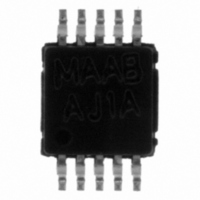
LMV422MMX National Semiconductor, LMV422MMX Datasheet

LMV422MMX
Specifications of LMV422MMX
Related parts for LMV422MMX
LMV422MMX Summary of contents
Page 1
... The LMV422 is designed for closed loop gains of plus two (or minus one) or greater. The LMV422 is offered in 10-Pin MSOP miniature package to ease the adoption in applications where board area premium. Typical Application © 2005 National Semiconductor Corporation Features n Supply voltage n Supply current per channel — Low power mode — ...
Page 2
... Absolute Maximum Ratings If Military/Aerospace specified devices are required, please contact the National Semiconductor Sales Office/ Distributors for availability and specifications. ESD Tolerance(Note 2) Human Body Machine Model V Differential IN + − Supply Voltage ( Storage Temperature Range Junction Temperature (Note 4) 5V Full Power Mode Electrical Characteristics Unless otherwise specified, all limits guaranteed for at T its apply at the temperature extremes ...
Page 3
Full Power Mode Electrical Characteristics Unless otherwise specified, all limits guaranteed for at T its apply at the temperature extremes. Symbol Parameter i Input-Referred Current Noise n t Time from Low Power Mode LF to Full Power Mode TH ...
Page 4
... Note 8: Slew rate is the average of the rising and falling slew rates. Note 9: Offset voltage average drift determined by dividing the change in V Connection Diagram Ordering Information Package Part Number LMV422MM 10-Pin MSOP LMV422MMX Simplified Schematic www.national.com , θ , and T . The maximum allowable power dissipation at any ambient temperature is J(MAX temperature extremes into the total temperature change ...
Page 5
Typical Performance Characteristics − Full Power Mode for Low Power Mode. Supply Current vs. Supply Voltage per Channel (Full Power Mode) Gain and Phase vs. Frequency Gain and Phase vs. Frequency Unless otherwise specified, V Supply Current ...
Page 6
Typical Performance Characteristics − Full Power Mode for Low Power Mode. (Continued) Phase Margin vs. Gain for Various Capacitive Load Input Offset Voltage vs. Output Voltage Noise vs. Frequency www.national.com Unless otherwise specified, V Phase Margin vs. ...
Page 7
Typical Performance Characteristics − Full Power Mode for Low Power Mode. (Continued) Small Signal Non-Inverting Response Small Signal Non-Inverting Response Large Signal Non-Inverting Response Unless otherwise specified, V Small Signal Non-Inverting Response 20109820 Small Signal Non-Inverting Response ...
Page 8
Application Information The LMV422 is a dual rail-to-rail output amplifier that can be switched between two active power modes. The power se- lect pin (PS) provides a method to optimize the power con- sumption, bandwidth and short circuit current. When ...
Page 9
Application Information Figure 3a AC COUPLED CIRCUITS The two power modes makes the LMV422 ideal for AC coupled circuit where the circuit needs to be kept active to maintain a quiescent charge on the coupling capacitors with minimum power consumption. ...
Page 10
... BANNED SUBSTANCE COMPLIANCE National Semiconductor manufactures products and uses packing materials that meet the provisions of the Customer Products Stewardship Specification (CSP-9-111C2) and the Banned Substances and Materials of Interest Specification (CSP-9-111S2) and contain no ‘‘Banned Substances’’ as defined in CSP-9-111S2. ...


