EL5411IRE Intersil, EL5411IRE Datasheet - Page 3
EL5411IRE
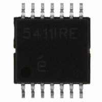
Manufacturer Part Number
EL5411IRE
Description
IC OP AMP QUAD 60MHZ RR 14HTSSOP
Manufacturer
Intersil
Datasheet
1.EL5111IWTZ-T7A.pdf
(18 pages)
Specifications of EL5411IRE
Amplifier Type
Voltage Feedback
Number Of Circuits
4
Output Type
Rail-to-Rail
Slew Rate
75 V/µs
Gain Bandwidth Product
32MHz
-3db Bandwidth
60MHz
Current - Input Bias
2nA
Voltage - Input Offset
3000µV
Current - Supply
10mA
Current - Output / Channel
65mA
Voltage - Supply, Single/dual (±)
4.5 V ~ 16.5 V, ±2.25 V ~ 8.25 V
Operating Temperature
-40°C ~ 85°C
Mounting Type
Surface Mount
Package / Case
14-TSSOP Exposed Pad, 14-eTSSOP 14-HTSSOP
Lead Free Status / RoHS Status
Contains lead / RoHS non-compliant
Available stocks
Company
Part Number
Manufacturer
Quantity
Price

Company:
Part Number:
EL5411IREZ
Manufacturer:
INTERSIL
Quantity:
48
Part Number:
EL5411IREZ
Manufacturer:
EL
Quantity:
20 000
Company:
Part Number:
EL5411IREZ-T13
Manufacturer:
JRC
Quantity:
1 500
Part Number:
EL5411IREZ-T13
Manufacturer:
INFERSIL
Quantity:
20 000


Absolute Maximum Ratings
Supply Voltage between V
Input Voltage . . . . . . . . . . . . . . . . . . . . . . . . . . V
Maximum Continuous Output Current . . . . . . . . . . . . . . . . . . . 65mA
Maximum Die Temperature . . . . . . . . . . . . . . . . . . . . . . . . . . +150°C
CAUTION: Stresses above those listed in “Absolute Maximum Ratings” may cause permanent damage to the device. This is a stress only rating and operation of the
device at these or any other conditions above those indicated in the operational sections of this specification is not implied.
IMPORTANT NOTE: All parameters having Min/Max specifications are guaranteed. Typ values are for information purposes only. Unless otherwise noted, all tests are
at the specified temperature and are pulsed tests, therefore: T
Electrical Specifications
NOTES:
INPUT CHARACTERISTICS
V
TCV
I
R
C
CMIR
CMRR
A
OUTPUT CHARACTERISTICS
V
V
I
I
POWER SUPPLY PERFORMANCE
PSRR
I
DYNAMIC PERFORMANCE
SR
t
BW
GBWP
PM
CS
d
d
1. Measured over operating temperature range.
2. Slew rate is measured on rising and falling edges.
3. NTSC signal generator used.
B
SC
OUT
S
S
PARAMETER
G
P
VOL
OS
IN
IN
OL
OH
OS
Input Offset Voltage
Average Offset Voltage Drift (Note 1)
Input Bias Current
Input Impedance
Input Capacitance
Common-Mode Input Range
Common-Mode Rejection Ratio
Open-Loop Gain
Output Swing Low
Output Swing High
Short-Circuit Current
Output Current
Power Supply Rejection Ratio
Supply Current
Slew Rate (Note 2)
Settling to +0.1% (A
-3dB Bandwidth
Gain-Bandwidth Product
Phase Margin
Channel Separation
Differential Gain (Note 3)
Differential Phase (Note 3)
S
+ and V
DESCRIPTION
3
S
V
- . . . . . . . . . . . . . . . . . . . .+18V
S
(T
+ = +5V, V
V
A
= +1)
= +25°C)
S
S
- - 0.5V, V
- = -5V, R
EL5111, EL5211, EL5411
J
= T
C
S
L
= T
V
V
for V
-4.5V ≤ V
I
I
V
No load (EL5111)
No load (EL5211)
No load (EL5411)
-4.0V ≤ V
(A
f = 5MHz (EL5211 and EL5411 only)
R
R
= 1kΩ to 0V, T
+0.5V
L
L
CM
CM
S
F
F
A
V
= -5mA
= 5mA
is moved from ±2.25V to ±7.75V
= R
= R
= +1), V
IN
= 0V
= 0V
G
G
from -5.5V to 5.5V
OUT
OUT
= 1kΩ and V
= 1kΩ and V
O
≤ 4.5V
≤ 4.0V, 20% to 80%
= 2V step
A
CONDITIONS
= +25°C, Unless Otherwise Specified
Thermal Information
Storage Temperature . . . . . . . . . . . . . . . . . . . . . . . .-65°C to +150°C
Ambient Operating Temperature . . . . . . . . . . . . . . . .-40°C to +85°C
Power Dissipation . . . . . . . . . . . . . . . . . . . . . . . . . . . . . See Curves
Pb-free reflow profile . . . . . . . . . . . . . . . . . . . . . . . . . .see link below
http://www.intersil.com/pbfree/Pb-FreeReflow.asp
OUT
OUT
= 1.4V
= 1.4V
4.85
MIN
-5.5
50
62
60
-4.92
±180
TYP
4.92
0.17
0.24
±65
110
2.5
70
70
80
10
75
80
60
32
50
3
7
2
1
2
5
-4.85
MAX
+5.5
4.5
7.5
15
60
15
May 7, 2007
µV/°C
UNIT
FN7119.7
V/µs
MHz
MHz
mV
GΩ
mA
mA
mA
mA
mA
nA
pF
dB
dB
dB
dB
ns
%
V
V
V
°
°
Related parts for EL5411IRE
Image
Part Number
Description
Manufacturer
Datasheet
Request
R

Part Number:
Description:
Intersil Corporation [CMOS Serial Controller Interface]
Manufacturer:
Intersil Corporation
Datasheet:
Part Number:
Description:
Manufacturer:
Intersil Corporation
Datasheet:
Part Number:
Description:
357-036-542-201 CARDEDGE 36POS DL .156 BLK LOPRO
Manufacturer:
Intersil Corporation
Datasheet:
Part Number:
Description:
1024-Word x 4-Bit LSI Static RAM
Manufacturer:
Intersil Corporation
Datasheet:
Part Number:
Description:
General Purpose NPN Transistor Arrays FN341.4
Manufacturer:
Intersil Corporation
Datasheet:
Part Number:
Description:
CMOS 16-Bit Microprocessor
Manufacturer:
Intersil Corporation
Datasheet:
Part Number:
Description:
Manufacturer:
Intersil Corporation
Datasheet:
Part Number:
Description:
Manufacturer:
Intersil Corporation
Datasheet:
Part Number:
Description:
Manufacturer:
Intersil Corporation
Datasheet:
Part Number:
Description:
Manufacturer:
Intersil Corporation
Datasheet:
Part Number:
Description:
CMOS 6-Bit Latch and Decoder Memory Interfaces
Manufacturer:
Intersil Corporation
Datasheet:
Part Number:
Description:
CA3046General Purpose NPN Transistor Arrays
Manufacturer:
Intersil Corporation
Datasheet:
Part Number:
Description:
Manufacturer:
Intersil Corporation
Datasheet:
Part Number:
Description:
TR909 DLC/FLC SLIC with Low Power Standby
Manufacturer:
Intersil Corporation
Datasheet:
Part Number:
Description:
Manufacturer:
Intersil Corporation
Datasheet: