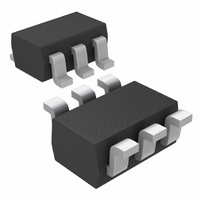
MAX4380EXT+T Maxim Integrated Products, MAX4380EXT+T Datasheet - Page 12

MAX4380EXT+T
Manufacturer Part Number
MAX4380EXT+T
Description
IC OP AMP R-R SS SC70-6
Manufacturer
Maxim Integrated Products
Datasheet
1.MAX4380EUTT.pdf
(16 pages)
Specifications of MAX4380EXT+T
Amplifier Type
Voltage Feedback
Number Of Circuits
1
Output Type
Rail-to-Rail
Slew Rate
485 V/µs
-3db Bandwidth
210MHz
Current - Input Bias
8.5µA
Voltage - Input Offset
3000µV
Current - Supply
7.5mA
Current - Output / Channel
75mA
Voltage - Supply, Single/dual (±)
4.5 V ~ 11 V, ±2.25 V ~ 5.5 V
Operating Temperature
-40°C ~ 85°C
Mounting Type
Surface Mount
Package / Case
SC-70-6, SC-88, SOT-363
Number Of Channels
1
Voltage Gain Db
63 dB
Common Mode Rejection Ratio (min)
70 dB
Input Offset Voltage
12 mV
Operating Supply Voltage
5 V, 9 V
Maximum Power Dissipation
245 mW
Maximum Operating Temperature
+ 85 C
Mounting Style
SMD/SMT
Maximum Dual Supply Voltage
+/- 5.5 V
Minimum Operating Temperature
- 40 C
Lead Free Status / RoHS Status
Lead free / RoHS Compliant
Gain Bandwidth Product
-
Lead Free Status / Rohs Status
Details
Ultra-Small, Low-Cost, 210MHz, Single-Supply
Op Amps with Rail-to-Rail Outputs and Disable
Figure 2. Driving a Capacitive Load Through an Isolation Resistor
Figure 3. Isolation Resistance vs. Capacitive Load
the capacitor is not isolated from the amplifier by a
resistor. A small isolation resistor (usually 10
placed before the reactive load prevents ringing and
oscillation. At higher capacitive loads, AC performance
is controlled by the interaction of the load capacitance
and the isolation resistor. Figure 5 shows the effect of a
15 isolation resistor on closed-loop response.
12
The MAX4380–MAX4384 are optimized for AC perfor-
mance. They are not designed to drive highly reactive
loads, which decrease phase margin and may produce
excessive ringing and oscillation. Figure 2 shows a cir-
cuit that eliminates this problem. Figure 3 is a graph of
the Optimal Isolation Resistor (R
Figure 4 shows how a capacitive load causes exces-
sive peaking of the amplifier’s frequency response if
Output Capacitive Loading and Stability
______________________________________________________________________________________
16
15
14
13
12
11
10
R
9
V
G
IN
0
50
100
ISOLATION RESISTANCE
vs. CAPACITIVE LOAD
MAX438 _
150
200
C
R
LOAD
F
250
(pF)
300
S
350
) vs. Capacitive Load.
400
R
ISO
450 500
C
L
V
OUT
to 15 )
MAX4380 TRANSISTOR COUNT: 66
MAX4381 TRANSISTOR COUNT: 132
MAX4382 TRANSISTOR COUNT: 196
MAX4383 TRANSISTOR COUNT: 264
MAX4384 TRANSISTOR COUNT: 264
Figure 4. Small-Signal Gain vs. Frequency with Load
Capacitance and No Isolation Resistor
Figure 5. Small-Signal Gain vs. Frequency with Load
Capacitance and 27 Isolation Resistor
-1
-2
-3
-4
6
5
4
3
2
1
0
100k
-1
-2
-3
-4
-5
-6
-7
3
2
1
0
100k
R
ISO
1M
= 15
FREQUENCY (Hz)
1M
C
L
C
= 10pF
L
10M
C
FREQUENCY (Hz)
= 120pF
L
Chip Information
C
= 68pF
L
= 5pF
10M
100M
C
L
= 15pF
100M
C
L
= 47pF
1G
1G


