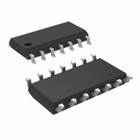
LM6134AIMX/NOPB National Semiconductor, LM6134AIMX/NOPB Datasheet - Page 5

LM6134AIMX/NOPB
Manufacturer Part Number
LM6134AIMX/NOPB
Description
IC OP AMP QUAD LOPWR RRIO 14SOIC
Manufacturer
National Semiconductor
Datasheet
1.LM6134AIMX.pdf
(16 pages)
Specifications of LM6134AIMX/NOPB
Amplifier Type
General Purpose
Number Of Circuits
4
Output Type
Rail-to-Rail
Slew Rate
14 V/µs
Gain Bandwidth Product
11MHz
Current - Input Bias
125nA
Voltage - Input Offset
1700µV
Current - Supply
390µA
Current - Output / Channel
3.5mA
Voltage - Supply, Single/dual (±)
1.8 V ~ 24 V, ±0.9 V ~ 12 V
Operating Temperature
-40°C ~ 85°C
Mounting Type
Surface Mount
Package / Case
14-SOIC (3.9mm Width), 14-SOL
Number Of Elements
4
Unity Gain Bandwidth Product
10MHz
Common Mode Rejection Ratio
60dB
Input Offset Voltage
2@5VmV
Input Bias Current
140nA
Single Supply Voltage (typ)
3/5/9/12/15/18V
Dual Supply Voltage (typ)
Not RequiredV
Voltage Gain In Db
100dB
Power Supply Rejection Ratio
78dB
Power Supply Requirement
Single
Shut Down Feature
No
Single Supply Voltage (min)
1.8V
Single Supply Voltage (max)
24V
Dual Supply Voltage (min)
Not RequiredV
Dual Supply Voltage (max)
Not RequiredV
Operating Temp Range
-40C to 85C
Operating Temperature Classification
Industrial
Mounting
Surface Mount
Pin Count
14
Package Type
SOIC N
Lead Free Status / RoHS Status
Lead free / RoHS Compliant
-3db Bandwidth
-
Lead Free Status / Rohs Status
Compliant
Other names
*LM6134AIMX/NOPB
Available stocks
Company
Part Number
Manufacturer
Quantity
Price
GBW
θ
G
THD + N
V
I
I
R
CMRR
PSRR
V
A
V
I
B
OS
S
Symbol
Symbol
m
OS
CM
V
O
IN
m
24V DC Electrical Characteristics
Unless otherwise specified, all limits guaranteed for T
Boldface limits apply at the temperature extreme
24V AC Electrical Characteristics
Unless otherwise specified, all limits guaranteed for T
Note 1: Absolute Maximum Ratings indicate limits beyond which damage to the device may occur. Operating Ratings indicate conditions for which the device is
intended to be functional, but specific performance is not guaranteed. For guaranteed specifications and the test conditions, see the Electrical characteristics.
Note 2: Human body model, 1.5 kΩ in series with 100 pF.
Note 3: Applies to both single-supply and split-supply operation. Continuous short circuit operation at elevated ambient temperature can result in exceeding the
maximum allowed junction temperature of 150˚C.
Note 4: The maximum power dissipation is a function of T
(T
Note 5: Typical Values represent the most likely parametric norm.
Note 6: All limits are guaranteed by testing or statistical analysis.
J(MAX)
− T
A
Gain-Bandwidth Product
Phase Margin
Gain Margin
Total Harmonic
Distortion and Noise
Input Offset Voltage
Input Bias Current
Input Offset Current
Input Resistance
Common Mode
Rejection Ratio
Power Supply
Rejection Ratio
Input Common-Mode
Voltage Range
Large Signal
Voltage Gain
Output Swing
Supply Current
)/θ
JA
. All numbers apply for packages soldered directly into a PC board.
Parameter
Parameter
J(MAX)
R
R
R
A
f = 10 kHz
0V ≤ V
0V ≤ V
2.7V ≤ V
R
R
Per Amplifier
V
L
L
L
L
L
, θ
= 10k, f = 20 kHz
= 10k
= 10k
= +1, V
= 10k
= 10k
J
J
JA
= 25˚C, V
= 25˚C, V
, and T
Conditions
Conditions
CM
CM
+
≤ 24V
≤ 24V
≤ 24V
O
A
= 20V
. The maximum allowable power dissipation at any ambient temperature is P
5
+
+
= 24V, V
= 24V, V
P-P
−
−
= 0V, V
= 0V, V
(Note 5)
(Note 5)
0.0015
−0.25
24.25
0.075
23.86
Typ
125
210
102
390
1.7
4.8
Typ
80
82
11
23
12
CM
CM
= V
= V
LM6134AI
LM6132AI
LM6134AI
LM6132AI
(Note 6)
(Note 6)
O
O
Limit
Limit
0.15
23.8
450
490
= V
= V
24
3
5
0
+
+
/2 and R
/2 and R
LM6134BI
LM6132BI
LM6134BI
LM6132BI
(Note 6)
(Note 6)
Limit
Limit
0.15
23.8
450
490
L
L
24
7
9
0
>
>
1 MΩ to V
1 MΩ to V
www.national.com
V max
V min
Units
V/mV
Units
MHz
max
max
max
mV
MΩ
min
deg
nA
nA
dB
dB
µA
dB
%
V
V
+
+
/2.
/2.
D
=


