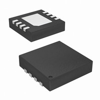
ISL24021IRT065Z Intersil, ISL24021IRT065Z Datasheet - Page 10

ISL24021IRT065Z
Manufacturer Part Number
ISL24021IRT065Z
Description
IC OPAMP RRIO 1A 25MHZ 8-TDFN
Manufacturer
Intersil
Datasheet
1.ISL24021IRT065Z-T13.pdf
(12 pages)
Specifications of ISL24021IRT065Z
Amplifier Type
Voltage Feedback
Number Of Circuits
1
Output Type
Rail-to-Rail
Slew Rate
19 V/µs
-3db Bandwidth
27MHz
Current - Input Bias
2nA
Voltage - Input Offset
1400µV
Current - Supply
2.2mA
Current - Output / Channel
300mA
Voltage - Supply, Single/dual (±)
4.5 V ~ 19 V, ±2.25 V ~ 9.5 V
Operating Temperature
-40°C ~ 85°C
Mounting Type
Surface Mount
Package / Case
8-TDFN
Lead Free Status / RoHS Status
Lead free / RoHS Compliant
Gain Bandwidth Product
-
.
.
Typical Application Circuit
A typical application of the ISL24021 is as a TFT-LCD V
driver (see Figure 27). A V
backplane common voltage of a TFT-LCD panel. Maintaining
the V
performance. The ability of the ISL24021 to source/sink
large peak short circuit currents make it ideal as a V
driver. The ±1A short circuit current capability combined with
a large bandwidth and fast settling time give the ISL24021
ideal V
for TFT-LCD applications.
FIGURE 27. TYPICAL APPLICATION CIRCUIT: TFT-LCD V
CALIBRATOR /
RESISTOR
LADDER
VCOM
4.7µF
V
V
COM
4.7µF
SS
SS
FIGURE 26. OUTPUT SERIES RESISTOR CIRCUIT
COM
INP
INP
0.1µF
FIGURE 25. OUTPUT SNUBBER CIRCUIT
voltage at a steady level is critical to panel
INN
INN
driver characteristics, and make it a great choice
INN
INP
THERMAL PAD CONNECTED
0.1µF
0.1µF
CONNECTED TO V
CONNECTED TO V
THERMAL PAD
THERMAL PAD
TO V
ISL24021
ISL24021
ISL24021
+
-
SS
V
COM
SS
10
driver maintains the
SS
NOTE: C
DEPENDING ON THE
APPLICATION
OUT
SS
0.1µF
0.1µF
+
STORAGE
C
R
STORAGE
R
C
SERIES
0.1µF
SNUBBER
SNUBBER
WILL VARY
4.7µF
4.7µF
4.7µF
PANEL
CAPACITANCE
Z
Z
V
L
L
OUT
COM
DD
OUT
V
V
TFT-LCD
DD
= 15V
DD
COM
COM
ISL24021
Power Dissipation
With a 300mA maximum continuous output drive capability, it
is possible to exceed the rated +150°C maximum junction
temperature. It is important to calculate the maximum power
dissipation of the ISL24021 for the application. Proper load
conditions will ensure that the ISL24021 junction temperature
stays within a safe operating region.
The ISL24021 has a built-in thermal protection, which
automatically shuts the output OFF (high impedance) when
the die temperature reaches +165°C. This ensures safe
operation and prevents internal damage to the device. When
the die cools by +15°C the output will automatically turn ON.
The maximum power dissipation allowed in a package is
determined according to Equation 1:
P
where:
• T
• T
• θ
• P
The actual maximum power dissipation of the IC is the total
quiescent supply current, times the total power supply
voltage, plus the power dissipation in the IC caused by the
loading condition.
Sourcing:
Sinking:
• V
• I
• V
• V
• V
• I
Device overheating can be avoided by calculating the
minimum resistive load condition, R
highest power dissipation. To find R
P
V
curve, Figure 28, for further information.
P
P
DMAX
DMAX
OUT
DMAX
DMAX
S
LOAD
JA
AMAX
JMAX
DMAX
S
DD
SS
OUT
= Device supply current
= Total supply voltage range (V
/I
= Thermal resistance of the package
= Negative supply voltage
LOAD
= Positive supply voltage
=
equations equal to each other and solve for
=
=
= Output voltage
= Load current
= Maximum junction temperature
= Maximum ambient temperature
T
-------------------------------------------- -
= Maximum power dissipation in the package
V
V
JMAX
S
S
. Reference the package power dissipation
×
×
I
I
S
S
Θ
–
JA
+
+
T
[
[
V
V
AMAX
DD
OUT
–
–
V
V
OUT
SS
)
)
×
×
I
I
LOAD
LOAD
LOAD
LOAD
DD
]
]
- V
, resulting in the
, set the two
SS
)
June 3, 2009
(EQ. 3)
FN6637.0
(EQ. 2)
(EQ. 1)


