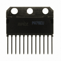
PA78EU Cirrus Logic Inc, PA78EU Datasheet - Page 2

PA78EU
Manufacturer Part Number
PA78EU
Description
IC PWR AMP 350V 200MA 12SIP
Manufacturer
Cirrus Logic Inc
Series
Apex Precision Power™r
Specifications of PA78EU
Amplifier Type
Power
Number Of Circuits
1
Slew Rate
350 V/µs
Gain Bandwidth Product
1MHz
Current - Input Bias
8.5pA
Voltage - Input Offset
8000µV
Current - Supply
700µA
Current - Output / Channel
150mA
Voltage - Supply, Single/dual (±)
20 V ~ 350 V, ±10 V ~ 175 V
Operating Temperature
-40°C ~ 125°C
Mounting Type
Through Hole
Package / Case
12-SIP
For Use With
598-1398 - KIT EVALUATION PA78/PA79598-1395 - EVALUATION KIT FOR PA78
Lead Free Status / RoHS Status
Lead free / RoHS Compliant
Output Type
-
-3db Bandwidth
-
Other names
598-1440
PA78EU
PA78EU
Available stocks
Company
Part Number
Manufacturer
Quantity
Price
Part Number:
PA78EU
Manufacturer:
APEX
Quantity:
20 000
Figure 2. Bridge Connected – A pair of PA78s drive the piezoelectric actuator and are powered by asymmetric power supplies
at +175V and -5V.
II. BRIDGE-CONNECTED PIEZOELECTRIC ACTuATOR
pable of delivering hundred of volts, peak-to-peak. Since a
typical actuator looks like virtually a pure capacitance to the
driving amplifier, almost all the power dissipation becomes
the burden of the driving amplifier. The circuit configuration
shown in Figure 2 fulfills these requirements. The source
voltage V
kHz. The circuit drives the actuator which is represented by
the 1-nanofarad capacitance in series with a 1 ohm resistance,
as depicted in Figure 2.
amplifiers can be connected in a bridge circuit
ured in this way, these ICs are able to deliver an output voltage
swing that is twice that of a single device. This configuration
also doubles the single-device slew rate. Another benefit is
that any nonlinearities become symmetrical, thereby reduc-
ing second-harmonic distortion when compared with a single
amplifier circuit.
ground-connected. When the left output VOUT
to 160V (Figure 3a) and the right output VOUT
160V to 10V (Figure 3b), a voltage swing of 300V (-150V to
+150V) develops across the load, as depicted in Figure 3c.
The overall gain of the two bridge-configured PA78s is +20,
so that 300V
required.
APEX MICROTECHNOLOGY CORPORATION • 5980 NORTH SHANNON ROAD • TuCSON, ARIZONA 85741 • uSA • APPLICATIONS HOTLINE: 1 (800) 546-2739
2
A piezoelectric actuator requires a high-voltage driver ca-
Figure 2 also illustrates how two PA78 power operational
A Floating Load — To say the load is floating means it is not
The outputs of the two amplifiers are now out of phase.
DRIvER
1
delivers 15V
P-P
is delivered to the piezoelectric actuator, as
P-P
at a frequency between zero to 80
B
A
1
descends from
swings from 10
. When config-
ply delivers +175V and -5V to the two amplifier modules
+V
headroom during the positive and negative excursions of both
VOUT
shown in Figure 3c will swing from +150V to -150V, it is actually
the Common Mode Input Range (CMR) positive and negative
values of the amplifier and specified in the PA78 data sheet that
will play a significant role in governing the values of +V
-V
negative is -V
the negative rail no closer than 3V. By choosing -V
-5V, both VOUT
10V, will approach the negative rail no closer than 15V.
most positive-going excursion of both VOUT
stay at least 2V below +V
at the output when the modules are delivering peak current.
In this application the peak current is approximately 75 mA.
There is a graph in the PA78 data sheet called "Output Volt-
age Swing" which denotes that if you are driving this much
current you are going to lose approximately 8 volts. The sum
of the two, 2V and 8V, is 10V which says the +V
at least 10V above the maximum voltage swing of 150V. By
choosing a +V
established.
As shown in Figure 2, a dual-source, asymmetric power sup-
Establishing +V
S
In the case of the PA78, the specified value of the CMR
For CMR positive, the value is +V
A second issue with regard to the +V
S
employed in this asymmetrical sourcing arrangement.
and -V
A
and VOUT
S
have been chosen so that there will be sufficient
S
S
+ 3V. This means the input should approach
A
of 175V, a headroom margin of 15V will be
and VOUT
B
S
. Though the output (VOUT
and -V
S
.
B
S
, having negative excursions to
headroom — The values of
S
S
- 2V. This means the
rail is the voltage drop
A
and VOUT
A
– VOUT
S
S
must be
equal to
B
S
must
2
.
and
B
)


