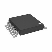
AD8367ARUZ Analog Devices Inc, AD8367ARUZ Datasheet - Page 2

AD8367ARUZ
Manufacturer Part Number
AD8367ARUZ
Description
IC AMP VGA 14TSSOP
Manufacturer
Analog Devices Inc
Series
X-AMP®r
Specifications of AD8367ARUZ
Amplifier Type
Variable Gain
Number Of Circuits
1
-3db Bandwidth
500MHz
Current - Input Bias
27µA
Current - Supply
26mA
Voltage - Supply, Single/dual (±)
2.7 V ~ 5.5 V
Operating Temperature
-40°C ~ 85°C
Mounting Type
Surface Mount
Package / Case
14-TSSOP
No. Of Amplifiers
1
Bandwidth
500MHz
No. Of Channels
1
Supply Voltage Range
2.7V To 5.5V
Amplifier Case Style
TSSOP
No. Of Pins
14
Operating Temperature Range
-40°C To +85°C
Current, Input Bias
27 μA
Current, Supply
26 mA
Package Type
TSSOP-14
Power Dissipation
250 mW
Resistance, Input
200 Ohms
Temperature, Operating, Range
-40 to +85 °C
Voltage, Input
±600 mV
Voltage, Output Swing
3.5 Vp-p
Voltage, Supply
2.7 to 5.5 V
Lead Free Status / RoHS Status
Lead free / RoHS Compliant
Output Type
-
Current - Output / Channel
-
Slew Rate
-
Gain Bandwidth Product
-
Voltage - Input Offset
-
Lead Free Status / Rohs Status
RoHS Compliant part
Electrostatic Device
Available stocks
Company
Part Number
Manufacturer
Quantity
Price
Company:
Part Number:
AD8367ARUZ
Manufacturer:
AD
Quantity:
5 510
Company:
Part Number:
AD8367ARUZ
Manufacturer:
ADI
Quantity:
875
Part Number:
AD8367ARUZ
Manufacturer:
ADI/亚德诺
Quantity:
20 000
Part Number:
AD8367ARUZ-REEL7
Manufacturer:
ADI/亚德诺
Quantity:
20 000
Part Number:
AD8367ARUZ-RL7
Manufacturer:
ADI/亚德诺
Quantity:
20 000
AD8367
TABLE OF CONTENTS
Features .............................................................................................. 1
Applications....................................................................................... 1
Functional Block Diagram .............................................................. 1
General Description ......................................................................... 1
Revision History ............................................................................... 2
Specifications..................................................................................... 3
Absolute Maximum Ratings............................................................ 5
Pin Configuration and Function Descriptions............................. 6
Typical Performance Characteristics ............................................. 7
Theory of Operation ...................................................................... 11
REVISION HISTORY
7/05—Rev. 0 to Rev. A
Changes to Format .............................................................Universal
Changes to General Description .................................................... 1
Changes to Table 1............................................................................ 3
Changes to Table 3............................................................................ 6
Changes to Figure 8.......................................................................... 7
Changes to Figure 9, Figure 12, and Figure 14 ............................. 8
Changes to Input and Output Interfaces Section ....................... 11
Changes to Output Centering Section and Figure 31................ 12
Changes to RMS Detection Section ............................................. 13
Changes to Figure 32, Table 4, and Table 5 ................................. 14
Changes to Figure 33, Figure 34, and
AGC Operation Section................................................................. 15
Changes to the Modifying the AGC Set Point Section.............. 16
Changes to Figure 38...................................................................... 17
Changes to Figure 42...................................................................... 19
Changes to Table 7.......................................................................... 20
Moved Table 7 to Page ................................................................... 20
Moved Characterization Setup and Methods Section to Page . 20
Moved Figure 45 to Page ............................................................... 20
Changes to Ordering Guide .......................................................... 21
Updated Outline Dimensions ....................................................... 21
10/01—Revision 0: Initial Version
ESD Caution.................................................................................. 5
Input Attenuator and Gain Control ......................................... 11
Input and Output Interfaces...................................................... 11
Power and Voltage Metrics........................................................ 12
Rev. A | Page 2 of 24
Applications..................................................................................... 14
Outline Dimensions ....................................................................... 21
Noise and Distortion.................................................................. 12
Output Centering ....................................................................... 12
RMS Detection ........................................................................... 13
Input and Output Matching...................................................... 14
VGA Operation .......................................................................... 15
Modulated Gain Mode .............................................................. 15
AGC Operation .......................................................................... 15
Modifying the AGC Setpoint.................................................... 16
Evaluation Board ........................................................................ 19
Characterization Setup and Methods ...................................... 20
Ordering Guide .......................................................................... 21


