HCPL-7800#500 Avago Technologies US Inc., HCPL-7800#500 Datasheet - Page 8
HCPL-7800#500
Manufacturer Part Number
HCPL-7800#500
Description
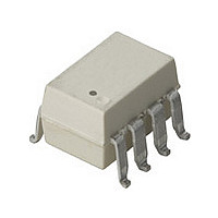
OPTOCOUPLER AMP 100KHZ 8-SMD
Manufacturer
Avago Technologies US Inc.
Datasheet
1.HCPL-7800-000E.pdf
(18 pages)
Specifications of HCPL-7800#500
Amplifier Type
Isolation
Number Of Circuits
1
-3db Bandwidth
100kHz
Current - Input Bias
500nA
Voltage - Input Offset
300µV
Current - Supply
10.9mA
Current - Output / Channel
16mA
Voltage - Supply, Single/dual (±)
4.5 V ~ 5.5 V
Operating Temperature
-40°C ~ 85°C
Mounting Type
Surface Mount
Package / Case
8-SMD Gull Wing
Operating Supply Voltage (typ)
5V
Lead Free Status / RoHS Status
Contains lead / RoHS non-compliant
Output Type
-
Slew Rate
-
Gain Bandwidth Product
-
Lead Free Status / RoHS Status
Not Compliant, Contains lead / RoHS non-compliant
Available stocks
Company
Part Number
Manufacturer
Quantity
Price


AC Electrical Specifications
Unless otherwise noted, all typicals and figures are at the nominal operating conditions of V
V
Package Characteristics
Parameter
V
(-3 dB) sine wave.
V
V
Signal Delay
(50 – 10%)
V
Signal Delay
(50 – 50%)
V
Signal Delay
(50 – 90%)
V
Rise/ Fall Time
(10 – 90%)
Common Mode
Transient
Immunity
Power Supply
Rejection
Parameter
Input-Output
Momentary Withstand
Voltage
Resistance
(Input-Output)
Capacitance
(Input-Output)
DD2
OUT
OUT
IN
IN
IN
OUT
to V
to V
to V
= 5 V and T
Bandwidth
Noise
OUT
OUT
OUT
A
= 25°C; all Min./Max. specifications are within the Recommended Operating Conditions.
Symbol
BW
N
t
t
t
t
CMTI
PSR
PD10
PD50
PD90
R/F
OUT
Symbol
V
R
C
I-O
ISO
I-O
Min.
50
10.0
Min.
3750
Typ.
100
31.5
2.03
3.47
4.99
2.96
15.0
170
Typ.
>10
1.2
Max.
3.3
5.6
9.9
6.6
9
Max.
Unit
kHz
mVrms
µs
kV/µs
mVrms
Unit
Vrms
Ω
pF
Test Conditions
V
V
V
step.
Measured at output of
MC34081 on Figure 15.
V
With recommended
application circuit.
IN+
IN+
IN+
CM
= 1 kV, T
= 200 mV
= 0.0 V
= 0 mV to 150 mV
RH < 50%,
t = 1 min.
T
V
ƒ = 1 MHz
Test Condition
A
I-O
= 25°C
= 500 V
A
pk-pk
= 25°C
DC
IN+
= 0, V
Fig.
12,13
14,15
16
Fig.
IN-
= 0 V, V
Note
13
14
15
Note
16,17
18
18
DD1
=
Related parts for HCPL-7800#500
Image
Part Number
Description
Manufacturer
Datasheet
Request
R

Part Number:
Description:
OPTOCOUPLER 2CH 2.5A 16-SOIC
Manufacturer:
Avago Technologies US Inc.
Datasheet:

Part Number:
Description:
OPTOCOUPLER LOG-OUT 10MBD 8SOIC
Manufacturer:
Avago Technologies US Inc.
Datasheet:

Part Number:
Description:
OPTOCOUPLER 1CH 2.5A 8-SMD
Manufacturer:
Avago Technologies US Inc.
Datasheet:

Part Number:
Description:
OPTOCOUPLER 1CH 0.6A 8-DIP
Manufacturer:
Avago Technologies US Inc.
Datasheet:
Part Number:
Description:
OPTOCOUPLER LOG-OUT 10MBD 8-SOIC
Manufacturer:
Avago Technologies US Inc.
Datasheet:

Part Number:
Description:
OPTOCOUPLER 1CH 2.5A 8-DIP
Manufacturer:
Avago Technologies US Inc.
Datasheet:

Part Number:
Description:
OPTOCOUPLER 2CH LOW IF 8-DIP
Manufacturer:
Avago Technologies US Inc.
Datasheet:

Part Number:
Description:
OPTOCOUPLER AMP 100KHZ 8-DIP
Manufacturer:
Avago Technologies US Inc.
Datasheet:
Part Number:
Description:
OPTOCOUPLER GATE DRV 2A 16-SOIC
Manufacturer:
Avago Technologies US Inc.
Datasheet:
Part Number:
Description:
OPTOCOUPLER GATE DRV 2A 16-SOIC
Manufacturer:
Avago Technologies US Inc.
Datasheet:

Part Number:
Description:
OPTOCOUPLER DAA PLC ISO 16SOIC
Manufacturer:
Avago Technologies US Inc.
Datasheet:
Part Number:
Description:
ISOLATOR DIG 100MBD 1CH 8-SOIC
Manufacturer:
Avago Technologies US Inc.
Datasheet:
Part Number:
Description:
ISOLATOR DIG 100MBD 2CH 8-SOIC
Manufacturer:
Avago Technologies US Inc.
Datasheet:
Part Number:
Description:
ISOLATOR DGTL 4CH 100MBD 16-SOIC
Manufacturer:
Avago Technologies US Inc.
Datasheet:
Part Number:
Description:
ISOLATOR HS DIG DUAL BI 8-SOIC
Manufacturer:
Avago Technologies US Inc.
Datasheet: