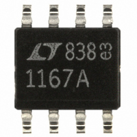
LT1167ACS8#PBF Linear Technology, LT1167ACS8#PBF Datasheet - Page 14

LT1167ACS8#PBF
Manufacturer Part Number
LT1167ACS8#PBF
Description
IC PREC INSTRMNT-AMP PROG 8-SOIC
Manufacturer
Linear Technology
Specifications of LT1167ACS8#PBF
Amplifier Type
Instrumentation
Number Of Circuits
1
Slew Rate
1.2 V/µs
Gain Bandwidth Product
1MHz
Current - Input Bias
50pA
Voltage - Input Offset
15µV
Current - Supply
900µA
Current - Output / Channel
27mA
Voltage - Supply, Single/dual (±)
4.6 V ~ 36 V, ±2.3 V ~ 18 V
Operating Temperature
0°C ~ 70°C
Mounting Type
Surface Mount
Package / Case
8-SOIC (3.9mm Width)
No. Of Amplifiers
1
Input Offset Voltage
15µV
Gain Db Min
1dB
Gain Db Max
10000dB
Bandwidth
1000kHz
Amplifier Output
Single Ended
Cmrr
140dB
Supply Voltage Range
± 2.3V To
Rohs Compliant
Yes
Lead Free Status / RoHS Status
Lead free / RoHS Compliant
Output Type
-
-3db Bandwidth
-
Available stocks
Company
Part Number
Manufacturer
Quantity
Price
APPLICATIO S I FOR ATIO
LT1167
To significantly reduce the effect of these out-of-band
signals on the input offset voltage of instrumentation
amplifiers, simple lowpass filters can be used at the
inputs. These filters should be located very close to the
input pins of the circuit. An effective filter configuration is
illustrated in Figure 5, where three capacitors have been
added to the inputs of the LT1167. Capacitors C
C
tors R
the input traces. Capacitor C
unwanted signal that would appear across the input traces.
An added benefit to using C
common mode rejection is not degraded due to common
mode capacitive imbalance. The differential mode and
common mode time constants associated with the capaci-
tors are:
Setting the time constants requires a knowledge of the
frequency, or frequencies of the interference. Once this
frequency is known, the common mode time constants
can be set followed by the differential mode time constant.
To avoid any possibility of inadvertently affecting the
signal to be processed, set the common mode time
constant an order of magnitude (or more) larger than the
differential mode time constant. Set the common mode
IN
IN
Figure 5. Adding a Simple RC Filter at the Inputs to an
Instrumentation Amplifier is Effective in Reducing Rectification
of High Frequency Out-of-Band Signals
14
XCM2
+
–
t
t
DM(LPF)
CM(LPF)
S1, 2
1.6k
1.6k
R
R
form lowpass filters with the external series resis-
S1
S2
EXTERNAL RFI
0.001 F
0.001 F
to any out-of-band signal appearing on each of
C
C
0.1 F
= (R
= (2)(R
XCM2
XCM1
FILTER
C
XD
S1, 2
S
U
)(C
)(C
XD
XCM1, 2
)
U
R
G
XD
XD
)
forms a filter to reduce any
+
–
f
is that the circuit’s AC
– 3dB
V
LT1167
V
W
+
–
500Hz
U
XCM1
1167 F05
V
OUT
and
time constants such that they do not degrade the LT1167’s
inherent AC CMR. Then the differential mode time con-
stant can be set for the bandwidth required for the appli-
cation. Setting the differential mode time constant close to
the sensor’s BW also minimizes any noise pickup along
the leads. To avoid any possibility of common mode to
differential mode signal conversion, match the common
mode time constants to 1% or better. If the sensor is an
RTD or a resistive strain gauge, then the series resistors
R
instrumentation amplifier.
“Roll Your Own”—Discrete vs Monolithic LT1167
Error Budget Analysis
The LT1167 offers performance superior to that of “roll
your own” three op amp discrete designs. A typical appli-
cation that amplifies and buffers a bridge transducer’s
differential output is shown in Figure 6. The amplifier, with
its gain set to 100, amplifies a differential, full-scale output
voltage of 20mV over the industrial temperature range. To
make the comparison challenging, the low cost version of
the LT1167 will be compared to a discrete instrumentation
amp made with the A grade of one of the best precision
quad op amps, the LT1114A. The LT1167C outperforms
the discrete amplifier that has lower V
comparable V
Table 1 shows how various errors are calculated and how
each error affects the total error budget. The table shows
the greatest differences between the discrete solution and
the LT1167 are input offset voltage and CMRR. Note that
for the discrete solution, the noise voltage specification is
multiplied by 2 which is the RMS sum of the uncorelated
noise of the two input amplifiers. Each of the amplifier
errors is referenced to a full-scale bridge differential
voltage of 20mV. The common mode range of the bridge
is 5V. The LT1114 data sheet provides offset voltage,
offset voltage drift and offset current specifications for the
matched op amp pairs used in the error-budget table. Even
with an excellent matched op amp like the LT1114, the
discrete solution’s total error is significantly higher than
the LT1167’s total error. The LT1167 has additional ad-
vantages over the discrete design, including lower com-
ponent cost and smaller size.
S1, 2
can be omitted, if the sensor is in proximity to the
OS
drift. The error budget comparison in
OS
, lower I
B
and


