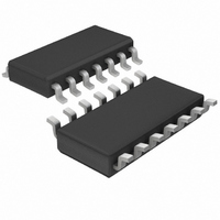
LT1259IS Linear Technology, LT1259IS Datasheet - Page 4

LT1259IS
Manufacturer Part Number
LT1259IS
Description
IC AMP DUAL CURR FDBK SD 14SOIC
Manufacturer
Linear Technology
Datasheet
1.LT1259CSPBF.pdf
(12 pages)
Specifications of LT1259IS
Amplifier Type
Current Feedback
Number Of Circuits
2
Slew Rate
1600 V/µs
-3db Bandwidth
130MHz
Current - Input Bias
20µA
Voltage - Input Offset
2000µV
Current - Supply
5mA
Current - Output / Channel
60mA
Voltage - Supply, Single/dual (±)
4 V ~ 30 V, ±2 V ~ 15 V
Operating Temperature
-40°C ~ 85°C
Mounting Type
Surface Mount
Package / Case
14-SOIC (3.9mm Width), 14-SOL
Lead Free Status / RoHS Status
Contains lead / RoHS non-compliant
Output Type
-
Gain Bandwidth Product
-
Available stocks
Company
Part Number
Manufacturer
Quantity
Price
Part Number:
LT1259IS
Manufacturer:
LINEAR/凌特
Quantity:
20 000
Part Number:
LT1259IS#PBF
Manufacturer:
LINEAR/凌特
Quantity:
20 000
Part Number:
LT1259IS#TRPBF
Manufacturer:
LINEAR/凌特
Quantity:
20 000
TYPICAL AC PERFOR A CE
LT1259/LT1260
ELECTRICAL CHARACTERISTICS
The
temperature range.
Note 1: A heat sink may be required depending on the power supply
voltage and how many amplifiers have their outputs short circuited.
Note 2: Commercial grade parts are designed to operate over the
temperature range of – 40 C to 85 C but are neither tested nor guaranteed
beyond 0 C to 70 C. Industrial grade parts specified and tested over
– 40 C to 85 C are available on special request. Consult factory.
Note 3: Ground pins are not internally connected. For best
performance, connect to ground.
Note 4: T
power dissipation P
TYPICAL PERFOR A CE CHARACTERISTICS
4
V
LT1259CN/LT1259IN: T
LT1259CS/LT1259IS: T
LT1260CNLT1260IN/: T
LT1260CS/LT1260IS: T
S
12
12
(V)
5
5
denotes specifications which apply over the specified operating
J
is calculated from the ambient temperature T
12
11
10
A
10
10
2
2
9
8
7
6
5
4
3
2
V
D
1
according to the following formulas:
12V Frequency Response, A
V
R
R
S
L
F
= R
= ±12V
= 150
J
J
J
J
GAIN
G
= T
= T
= T
= T
= 1.5k
R
150
150
150
150
L
A
A
A
A
FREQUENCY (MHz)
( )
+ (P
+ (P
+ (P
+ (P
W
10
D
D
D
D
• 110 C/W)
• 100 C/W)
• 70 C/W)
• 70 C/W)
W U
U
PHASE
R
1.5k
1.1k
1.1k
825
F
( )
LT1259/60 • TPC01
100
V
= 2
A
and the
0
–20
–40
–60
–80
–100
–120
–140
–160
–180
–200
R
1.5k
1.1k
90.9
G
121
( )
– 3dB BW (MHz)
SMALL SIGNAL
Note 5: The supply current of the LT1259/LT1260 has a negative
temperature coefficient. See Typical Performance Characteristics.
Note 6: Slew rate is measured at 5V on a 10V output signal while
operating on 15V supplies with R
Note 7: Turn-on delay time is measured while operating on 5V
supplies with R
from control input to appearance of 0.5V at the output, for V
Likewise, turn-off delay time is measured from control input to
appearance of 0.5V on the output for V
Note 8: Differential gain and phase are measured using a Tektronix
TSG120YC/NTSC signal generator and a Tektronix 1780R Video
Measurement Set. The resolution of this equipment is 0.1% and 0.1 .
Six identical amplifier stages were cascaded giving an effective
resolution of 0.016% and 0.016 .
130
93
69
61
26
25
24
23
22
21
20
19
18
17
16
1
12V Frequency Response, A
F
= 1k, R
GAIN
FREQUENCY (MHz)
G
= 110 and R
0.1dB BW (MHz)
SMALL SIGNAL
10
PHASE
53
40
20
16
F
= 1k, R
IN
L
V
R
R
R
LT1259/60 • TPC01
S
= 0.1V.
L
F
G
= 150 . The t
= 1.1k
= ±12V
= 150
= 121
G
100
V
= 110 and R
= 10
0
–20
–40
–60
–80
–100
–120
–140
–160
–180
–200
SMALL SIGNAL
PEAKING (dB)
ON
0.13
0.1
is measured
0
0
L
IN
= 1k.
= 0.1V.


