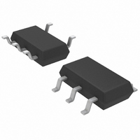
LTC6101BIS5#TRMPBF Linear Technology, LTC6101BIS5#TRMPBF Datasheet - Page 13

LTC6101BIS5#TRMPBF
Manufacturer Part Number
LTC6101BIS5#TRMPBF
Description
IC AMP CURRENT SENSE TSOT23-5
Manufacturer
Linear Technology
Type
Current Sense Amplifierr
Datasheet
1.LTC6101HVAHS5TRMPBF.pdf
(20 pages)
Specifications of LTC6101BIS5#TRMPBF
Amplifier Type
Current Sense
Number Of Circuits
1
Gain Bandwidth Product
200kHz
Current - Input Bias
100nA
Voltage - Input Offset
150µV
Current - Supply
375µA
Current - Output / Channel
1mA
Voltage - Supply, Single/dual (±)
4 V ~ 60 V
Operating Temperature
-40°C ~ 85°C
Mounting Type
Surface Mount
Package / Case
TSOT-23-5, TSOT-5, TSOP-5
Number Of Channels
1
Number Of Elements
1
Power Supply Requirement
Single
Input Offset Voltage
0.45@60VmV
Input Bias Current
0.17@60VnA
Single Supply Voltage (typ)
5/9/12/15/18/24/28V
Dual Supply Voltage (typ)
Not RequiredV
Power Supply Rejection Ratio
110dB
Rail/rail I/o Type
No
Single Supply Voltage (min)
4V
Single Supply Voltage (max)
60V
Dual Supply Voltage (min)
Not RequiredV
Dual Supply Voltage (max)
Not RequiredV
Operating Temp Range
-40C to 85C
Operating Temperature Classification
Industrial
Mounting
Surface Mount
Pin Count
5
Package Type
TSOT-23
Lead Free Status / RoHS Status
Lead free / RoHS Compliant
Output Type
-
-3db Bandwidth
-
Slew Rate
-
Lead Free Status / Rohs Status
Compliant
Available stocks
Company
Part Number
Manufacturer
Quantity
Price
APPLICATIONS INFORMATION
Output Filtering
The output voltage, V
makes fi ltering straightforward. Any circuit may be used
which generates the required Z
response. For example, a capacitor in parallel with R
will give a low pass response. This will reduce unwanted
noise from the output, and may also be useful as a charge
reservoir to keep the output steady while driving a switch-
ing circuit such as a mux or ADC. This output capacitor
in parallel with an output resistor will create a pole in the
output response at:
Useful Equations
Input Voltage: V
Current Gain:
f
Voltage Gain:
Transconductance:
Transimpedance:
– 3dB
=
2 • π • R
I
V
SENSE
I
OUT
SENSE
V
OUT
SENSE
1
OUT
I
SENSE
V
OUT
• C
V
OUT
=
I
SENSE
=I
OUT
OUT
=
, is simply I
R
SENSE
R
SENSE
R
R
=R
OUT
OUT
IN
IN
=
SENSE
R
• R
to get the desired fi lter
1
IN
SENSE
•
OUT
R
R
OUT
IN
• Z
OUT
. This
OUT
Input Common Mode Range
The inputs of the LTC6101 can function from 1.5V below
the positive supply to 0.5V above it. Not only does this
allow a wide V
ence to be separate from the positive supply (Figure 5).
Note that the difference between V
more than the common mode range listed in the Electrical
Characteristics table. If the maximum V
500mV, the LTC6101 may monitor its own supply current,
as well as that of the load (Figure 6).
R
R
SENSE
SENSE
V
BATTERY
LOAD
LOAD
V
+
Figure 5. V
Load Supply (V
Figure 6. LTC6101 Supply Current
Monitored with Load
R
R
SENSE
IN
IN
LTC6101/LTC6101HV
+IN
+IN
V
V
–
–
range, it also allows the input refer-
LTC6101
LTC6101
+
Powered Separately from
+
+
BATT
)
–
–
BATT
–IN
–IN
V
OUT
V
OUT
and V
+
+
SENSE
6101 F05
V
+
+
R
OUT
is less than
must be no
R
OUT
V
OUT
6101 F06
13
V
OUT
6101fg


