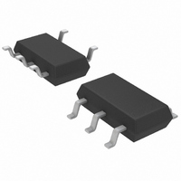
LT6220CS5#TRPBF Linear Technology, LT6220CS5#TRPBF Datasheet - Page 16

LT6220CS5#TRPBF
Manufacturer Part Number
LT6220CS5#TRPBF
Description
IC OPAMP PREC LP R-R TSOT23-5
Manufacturer
Linear Technology
Datasheet
1.LT6220CS5TRMPBF.pdf
(20 pages)
Specifications of LT6220CS5#TRPBF
Amplifier Type
General Purpose
Number Of Circuits
1
Output Type
Rail-to-Rail
Slew Rate
20 V/µs
Gain Bandwidth Product
60MHz
Current - Input Bias
250nA
Voltage - Input Offset
700µV
Current - Supply
1mA
Current - Output / Channel
50mA
Voltage - Supply, Single/dual (±)
2.2 V ~ 12.6 V, ±1.1 V ~ 6.3 V
Operating Temperature
0°C ~ 70°C
Mounting Type
Surface Mount
Package / Case
TSOT-23-5, TSOT-5, TSOP-5
Lead Free Status / RoHS Status
Lead free / RoHS Compliant
-3db Bandwidth
-
Available stocks
Company
Part Number
Manufacturer
Quantity
Price
LT6220/LT6221/LT6222
PACKAGE DESCRIPTIO
As the signal level increases though, the output of the op
amp goes more negative. At 12.5µA of photodiode cur-
rent, the 100kΩ gain dictates that the LT6220 output will
be about 1.25V below ground. However, at that point the
emitter of Q2 will be at ground, and the base of Q1 will be
1V below ground. Thus, Q1 turns on and photodiode
current starts to flow through R2. The transimpedance
gain is therefore now reduced to R1||R2, or about 3.1kΩ.
The circuit response is shown in Figure 3. Note the smooth
transition between the two operating gains, as well as the
linearity.
Single 3V Supply, 1MHz, 4th Order Butterworth Filter
The circuit shown in Figure 4 makes use of the low voltage
operation and the wide bandwidth of the LT6221 to create
a DC accurate 1MHz 4th order lowpass filter powered from
a 3V supply. The amplifiers are configured in the inverting
mode for the lowest distortion and the output can swing
rail-to-rail for maximum dynamic range. Figure 5 displays
the frequency response of the filter. Stopband attenuation
is greater than 100dB at 50MHz.
16
100µA/DIV
CURRENT
0.5V/DIV
Figure 3. Stepped-Gain Photodiode Amplifier Response
PHOTO
V
OUT
V
V
S
IN
/2
5µs/DIV
909Ω
909Ω
220pF
2.67k
U
Figure 4. 3V, 1MHz, 4th Order Butterworth Filter
622012 F03
47pF
–
+
1/2 LT6221
1.1k
Differential-In/Differential-Out Amplifier
The circuit of Figure 6 shows the LT6222 applied as a
buffered differential-in differential-out amplifier with a
gain of 2. Op amps A and B are configured as simple unity-
gain buffers, offering high input impedance to upstream
circuitry. Resistors R1 and R2 perform an averaging
function on the common mode input voltage and R3
attenuates it by a factor of 2/3 and references it to the
voltage source V
V
D. The other four resistors set gains of +3 from the
noninverting input and –2 through the inverting path. Thus
the output voltage of the upper path is:
ICM
–OUT = 3 • (2/3 • V
1.1k
, is placed at the noninverting inputs of op amps C and
2.21k
470pF
–100
–120
• (V
= 2V
= V
–20
–40
–60
–80
20
Figure 5. Frequency Response of Filter
0
1k
OCM
ICM
22pF
ICM
–
+
1/2 LT6221
+ V
OCM
– V
+ V
10k
3V
DIFF
DIFF
. The resultant voltage, V
OCM
622012 F04
ICM
FREQUENCY (Hz)
100k
/2)
– 2V
+ 1/3 • V
V
1M
ICM
OUT
– V
OCM
10M
DIFF
622012 F05
) – 2
100M
MID
= 2/3 •
622012fa


