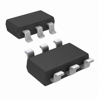
LMP8645MKE/NOPB National Semiconductor, LMP8645MKE/NOPB Datasheet - Page 4

LMP8645MKE/NOPB
Manufacturer Part Number
LMP8645MKE/NOPB
Description
IC AMP CURRENT SENSE 6TSOT
Manufacturer
National Semiconductor
Type
Current Sense Ampr
Datasheet
1.LMP8645MKENOPB.pdf
(16 pages)
Specifications of LMP8645MKE/NOPB
Amplifier Type
Current Sense
Number Of Circuits
1
Slew Rate
0.6 V/µs
-3db Bandwidth
860kHz
Current - Input Bias
13µA
Voltage - Input Offset
1700µV
Current - Supply
2.2mA
Current - Output / Channel
5mA
Voltage - Supply, Single/dual (±)
2.7 V ~ 12 V
Operating Temperature
-40°C ~ 125°C
Mounting Type
Surface Mount
Package / Case
TSOT-23-6, TSOT-6
Number Of Channels
1
Number Of Elements
2
Power Supply Requirement
Single
Common Mode Rejection Ratio
95dB
Input Offset Voltage
1@5VmV
Input Bias Current
22@5VnA
Single Supply Voltage (typ)
3/5/9V
Dual Supply Voltage (typ)
Not RequiredV
Power Supply Rejection Ratio
90dB
Rail/rail I/o Type
No
Single Supply Voltage (min)
2.7V
Single Supply Voltage (max)
12V
Dual Supply Voltage (min)
Not RequiredV
Dual Supply Voltage (max)
Not RequiredV
Operating Temp Range
-40C to 125C
Operating Temperature Classification
Automotive
Mounting
Surface Mount
Pin Count
6
Package Type
TSOT
No. Of Amplifiers
1
Bandwidth
990kHz
Cmrr
95dB
Supply Voltage Range
2.7V To 12V
Supply Current
610µA
Rohs Compliant
Yes
Lead Free Status / RoHS Status
Lead free / RoHS Compliant
Output Type
-
Gain Bandwidth Product
-
Lead Free Status / Rohs Status
Compliant
Other names
LMP8645MKETR
www.national.com
V
TCV
I
e
V
Gain A
Gm
PSRR
CMRR
BW
SR
I
V
I
C
B
S
OUT
ni
OS
SENSE(MAX)
OUT
LOAD
12V Electrical Characteristics
Unless otherwise specified, all limits guaranteed for at T
= 10 MΩ. Boldface limits apply at the temperature extremes.
Note 1: Absolute Maximum Ratings indicate limits beyond which damage to the device may occur. Operating Ratings indicate conditions for which the device
is intended to be functional, but specific performance is not guaranteed. For guaranteed specifications and the test conditions, see the Electrical Characteristics
Tables.
Note 2: Human Body Model, applicable std. MIL-STD-883, Method 3015.7. Machine Model, applicable std. JESD22-A115-A (ESD MM std. of JEDEC) Field-
Induced Charge-Device Model, applicable std. JESD22-C101-C (ESD FICDM std. of JEDEC).
Note 3: The maximum power dissipation must be derated at elevated temperatures and is dictated by T
allowable power dissipation P
Note 4: Electrical Table values apply only for factory testing conditions at the temperature indicated. Factory testing conditions result in very limited self-heating
of the device such that T
T
Note 5: Typical values represent the most likely parametric norm at the time of characterization. Actual typical values may vary over time and will also depend
on the application and configuration. The typical values are not tested and are not guaranteed on shipped production material.
Note 6: All limits are guaranteed by testing, design, or statistical analysis.
Note 7: Offset voltage temperature drift is determined by dividing the change in V
Symbol
A
.
OS
V
Input Offset Voltage
Input Offset Voltage Drift
(Note
Input Bias Current
Input Voltage Noise
Max Input Sense Voltage
Adjustable Gain Setting
Transconductance
Accuracy
Gm drift
Power Supply Rejection Ratio
Common Mode Rejection Ratio
−3 dB Bandwidth
Slew Rate
Supply Current
Maximum Output Voltage
Minimum Output Voltage
Output current
Max Output Capacitance Load
(Note
7,
9)
J
Note
(Note
= T
(Note
Parameter
A
DMAX
. No guarantee of parametric performance is indicated in the electrical tables under conditions of internal self-heating where T
9)
9)
(Note
= (T
8,
(Note
(Note
J(MAX)
Note
(Note
9)
9)
(Note
- T
10)
9)
(Note
9)
A
)/ θ
JA
9)
9) V
or the number given in Absolute Maximum Ratings, whichever is lower.
V
V
V
f > 10 kHz, R
V
V
V
−40°C to 125°C, V
V
LMP8645HV 2.1V <V
LMP8645 2.1V <V
–2V <V
R
C
R
C
R
C
V
to 500 mV, C
V
V
V
V
Sourcing, V
Sinking, V
CM
CM
CM
CM
CM
CM
CM
CM
CM
CM
CM
CM
CM
G
L
G
L
G
L
= 30 pF, R
= 30 pF, R
= 30 pF, R
= 10 kΩ, C
= 25 kΩ, C
= 50 kΩ, C
(Note
= 2.1V
= 2.1V
= 2.1V
=12V, R
= 12V
= 2.1V
= 2.1V
=2.1V, 2.7V <V
= 5V, C
= 2.1V
= −2V
= 12V, R
= 2.1V
CM
A
= 25°C, V
OUT
4)
< 2V
OUT
G
G
G
L
G
= 5.25V, Rg= 150kΩ
L
L
L
= 4 pF, V
G
G
G
= 5 kΩ
= 1MΩ
= 1MΩ
= 1MΩ
= 30 pF, R
= 500kΩ
= 5 kΩ
= 5.25V, Rg= 150kΩ
4
= 4 pF, V
= 4 pF, V
Condition
= 4 pF V
CM
CM
OS
S
+
=V
< 42V
at the temperature extremes by the total temperature change.
< 12V
CM
=2.1V
SENSE
+
-V
< 76V
SENSE
SENSE
SENSE
L
=1MΩ
-
, V
from 100 mV
+
= 400 mV,
= 400 mV,
=400 mV,
= 12V, V
J(MAX)
, θ
JA
−
, and the ambient temperature, T
= 0V, −2V < V
(Note
10.2
Min
-1.7
-3.4
90
95
60
-1
-2
1
6)
(Note
2200
CM
Typ
120
600
200
860
260
140
555
0.6
13
30
5
5
< 76V, R
5)
(Note
2900
3110
Max
100
140
765
920
1.7
3.4
23
24
A
1
7
2
g
. The maximum
= 25kΩ, R
6)
ppm /°C
nV/
μV/°C
Units
µA/V
V/µs
kHz
mV
mV
V/V
mV
mA
μA
dB
dB
uA
pF
%
V
J
L
>


