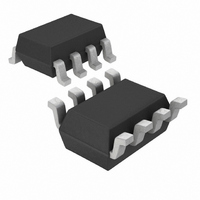
MAX9618AXA+T Maxim Integrated Products, MAX9618AXA+T Datasheet - Page 6

MAX9618AXA+T
Manufacturer Part Number
MAX9618AXA+T
Description
IC OP AMP RRIO LOW POWER SC70-8
Manufacturer
Maxim Integrated Products
Datasheet
1.MAX9617EVKIT.pdf
(12 pages)
Specifications of MAX9618AXA+T
Amplifier Type
Chopper (Zero-Drift)
Number Of Circuits
2
Output Type
Rail-to-Rail
Slew Rate
0.7 V/µs
Gain Bandwidth Product
1.5MHz
Current - Input Bias
10pA
Voltage - Input Offset
0.8µV
Current - Supply
59µA
Current - Output / Channel
150mA
Voltage - Supply, Single/dual (±)
1.6 V ~ 5.5 V, ±0.8 V ~ 2.75 V
Operating Temperature
-40°C ~ 125°C
Mounting Type
Surface Mount
Package / Case
SC-70-8
Common Mode Rejection Ratio (min)
116 dB
Input Voltage Range (max)
5.5 V
Input Voltage Range (min)
1.8 V
Input Offset Voltage
0.8 uV
Input Bias Current (max)
3.5 nA
Supply Current
59 uA
Maximum Power Dissipation
245 mW
Maximum Operating Temperature
+ 125 C
Minimum Operating Temperature
- 40 C
Mounting Style
SMD/SMT
Lead Free Status / RoHS Status
Lead free / RoHS Compliant
-3db Bandwidth
-
Lead Free Status / Rohs Status
Lead free / RoHS Compliant
Other names
MAX9618AXA+T
(V
Single/Dual SC70, Zero-Drift,
High-Efficiency, 1.5MHz Op Amps with RRIO
6
MAX9617
DD
TOP VIEW
LARGE-SIGNAL STEP RESPONSE
______________________________________________________________________________________
5, 6
—
—
—
—
—
—
—
= +3.3V, V
1
2
3
4
GND
IN+
IN-
vs. TIME
100Fs/div
MAX9618
1
2
3
GND
+
—
—
—
—
4
8
1
2
3
5
6
7
MAX9617
= 0V, outputs have R
SC70
PIN
100mV
MAX9619
MAX9617 toc20
P-P
—
—
—
—
—
—
1
2
3
4
6
5
6
5
4
V
V
OUT
500mV/div
DD
DD
MAX9620
OUTA
INA+
INA-
GND
L
—
—
—
—
—
—
—
= 100kI connected to V
1
2
3
4
5
1
2
3
4
10,000
1000
Typical Operating Characteristics (continued)
100
+
0.1
MAX9618
SC70
NAME
SHDN
OUTA
OUTB
INA+
INB+
GND
OUT
INA-
INB-
V
A
V
IN+
IN-
IN
V
DD
= 1V/V
= 100mV
vs. ISOLATION RESISTOR
1
ISOLATION RESISTOR (I)
CAPACITIVE LOAD
P-P
UNSTABLE
Positive Input
Ground
Negative Input
Output
Positive Supply Voltage. Bypass to GND with a 0.1FF capacitor.
Shutdown. Pull shutdown low to activate shutdown mode.
Channel A Output
Channel A Negative Input
Channel A Positive Input
Channel B Positive Input
Channel B Negative Input
Channel B Output
8
7
6
5
V
OUTB
INB-
INB+
DD
10
DD
/2. T
GND
IN+
IN-
A
100
1
2
3
= +25NC, unless otherwise specified.)
+
MAX9619
SC70
1000
FUNCTION
6
5
4
V
SHDN
OUT
DD
Pin Configurations
GND
POWER-UP TIME
IN+
IN-
Pin Description
20Fs/div
1
2
3
+
MAX9620
SC70
MAX9617 toc22
5 V
4
OUT
SHDN
1V/div
OUT
1V/div
DD


