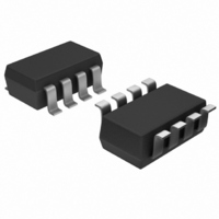
MAX4232AKA+T Maxim Integrated Products, MAX4232AKA+T Datasheet - Page 11

MAX4232AKA+T
Manufacturer Part Number
MAX4232AKA+T
Description
IC OP AMP R-R W/SD SOT23-8
Manufacturer
Maxim Integrated Products
Datasheet
1.MAX4231EVKIT.pdf
(28 pages)
Specifications of MAX4232AKA+T
Amplifier Type
General Purpose
Number Of Circuits
2
Output Type
Rail-to-Rail
Slew Rate
10 V/µs
Gain Bandwidth Product
10MHz
Current - Input Bias
50pA
Voltage - Input Offset
850µV
Current - Supply
1.2mA
Current - Output / Channel
200mA
Voltage - Supply, Single/dual (±)
2.7 V ~ 5.5 V, ±1.35 V ~ 2.5 V
Operating Temperature
-40°C ~ 125°C
Mounting Type
Surface Mount
Package / Case
SOT-23-8
Number Of Channels
2
Voltage Gain Db
100 dB
Common Mode Rejection Ratio (min)
52 dB
Input Offset Voltage
6 mV
Operating Supply Voltage
3 V, 5 V
Maximum Power Dissipation
714 mW
Maximum Operating Temperature
+ 125 C
Mounting Style
SMD/SMT
Maximum Dual Supply Voltage
+/- 2.5 V
Minimum Operating Temperature
- 40 C
Lead Free Status / RoHS Status
Lead free / RoHS Compliant
-3db Bandwidth
-
Lead Free Status / Rohs Status
Details
Other names
MAX4232AKA+T
MAX4232AKA+TTR
MAX4232AKA+TTR
To improve step response when R′ > 2kΩ, connect
small capacitor C
put. Choose C
where R
ting resistor (Figure 5).
The MAX4230–MAX4234 have a high tolerance for
capacitive loads. They are stable with capacitive loads
up to 780pF. Figure 6 is a graph of the stable operating
region for various capacitive loads vs. resistive loads.
Figures 7 and 8 show the transient response with
excessive capacitive loads (1500pF), with and without
the addition of an isolation resistor in series with the
output. Figure 9 shows a typical noninverting capaci-
tive-load-driving circuit in the unity-gain configuration.
Figure 5. Inverting and Noninverting Amplifiers with Feedback
Compensation
Rail-to-Rail I/O Op Amps with Shutdown in SC70
V
INVERTING
NONINVERTING
IN
f
is the feedback resistor and R is the gain-set-
R
R
f
as follows:
V
IN
f
______________________________________________________________________________________
between the inverting input and out-
C
f
= 8(R / R
MAX4230
MAX4230
Driving Capacitive Loads
C
R
R
C
f
f
f
f
f
R′ = R || R
R
) [pf]
R′ = R || R
R
f
C
f
C
f
f
= RC
= RC
High-Output-Drive, 10MHz, 10V/µs,
IN
f
IN
f
V
V
OUT
OUT
Figure 6. Capacitive-Load Stability
Figure 7. Small-Signal Transient Response with Excessive
Capacitive Load
Figure 8. Small-Signal Transient Response with Excessive
Capacitive Load with Isolation Resistor
20mV/div
20mV/div
20mV/div
20mV/div
2500
2000
1500
1000
500
0
1
V
R
DD
L
V
R
V
R
TO V
DD
L
DD
L
= 5.0V
= 100kΩ, R
= 100kΩ, R
= 3.0V, C
= 3.0V, C
10
DD
/2
RESISTIVE LOAD (Ω)
L
L
100
ISO
ISO
= 1500pF
STABLE
= 1500pF
1µs/div
1µs/div
= 0Ω
= 39Ω
UNSTABLE
1k
10k
100k
11


