MC3403PG ON Semiconductor, MC3403PG Datasheet - Page 5
MC3403PG
Manufacturer Part Number
MC3403PG
Description
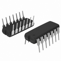
IC OPAMP QUAD DIFF INPUT 14DIP
Manufacturer
ON Semiconductor
Specifications of MC3403PG
Amplifier Type
General Purpose
Number Of Circuits
4
Slew Rate
0.6 V/µs
Gain Bandwidth Product
1MHz
Current - Input Bias
200nA
Voltage - Input Offset
2000µV
Current - Supply
2.8mA
Current - Output / Channel
20mA
Voltage - Supply, Single/dual (±)
3 V ~ 36 V, ±1.5 V ~ 18 V
Operating Temperature
0°C ~ 70°C
Mounting Type
Through Hole
Package / Case
14-DIP (0.300", 7.62mm)
Number Of Channels
4
Common Mode Rejection Ratio (min)
70 dB
Input Voltage Range (max)
Positive Rail - 2 V
Input Voltage Range (min)
Negative Rail
Input Offset Voltage
10 mV
Input Bias Current (max)
500 nA
Operating Supply Voltage
36 V
Supply Current
2.8 mA
Maximum Operating Temperature
+ 70 C
Minimum Operating Temperature
0 C
Dual Supply Voltage
+/- 3 V, +/- 5 V, +/- 9 V
Maximum Dual Supply Voltage
+/- 18 V
Minimum Dual Supply Voltage
+/- 1.5 V
Mounting Style
Through Hole
Shutdown
No
Supply Voltage (max)
36 V
Supply Voltage (min)
3 V
Technology
Bipolar
Voltage Gain Db
106.02 dB
Bandwidth
1 MHz
Channel Separation
-120
Common Mode Rejection Ratio
90
Current, Input Bias
-200 nA
Current, Input Offset
30 nA
Current, Output
20 mA
Current, Supply
2.8 mA
Number Of Amplifiers
Quad
Package Type
PDIP-14
Temperature, Operating, Range
-40 to +85 °C
Time, Fall
0.35 μs
Time, Rise
0.35 μs
Voltage, Gain
200 V/mV
Voltage, Input
±18 VDC
Voltage, Offset
2 mV
Voltage, Output, High
±10 V
Voltage, Output, Low
±10 V
Voltage, Supply
3 to 36 V
Lead Free Status / RoHS Status
Lead free / RoHS Compliant
Output Type
-
-3db Bandwidth
-
Lead Free Status / Rohs Status
Lead free / RoHS Compliant
Other names
MC3403PGOS
Available stocks
Company
Part Number
Manufacturer
Quantity
Price
Company:

Part Number:
MC3403PG
Manufacturer:
ON Semiconductor
Quantity:
1 799
Part Number:
MC3403PG
Manufacturer:
ON/安森美
Quantity:
20 000


compensated, two−stage operational amplifiers. The first
stage of each consists of differential input device Q24 and
Q22 with input buffer transistors Q25 and Q21 and the
differential to single ended converter Q3 and Q4. The first
The MC3403/3303 is made using four internally
−5.0
5.0
30
25
20
15
10
*Note Class A B output stage produces distortion less sinewave.
0
1.0 k
A
V
T
= 100
A
Figure 2. Inverter Pulse Response
= 25°C
Figure 3. Sine Wave Response
Figure 5. Power Bandwidth
50 ms/DIV
10 k
f, FREQUENCY (Hz)
20 ms/DIV
100 k
−
+
−15 V
+15 V
CIRCUIT DESCRIPTION
http://onsemi.com
10 k
V
O
1.0 M
5
stage performs not only the first stage gain function but also
performs the level shifting and Transconductance reduction
functions. By reducing the Transconductance, a smaller
compensation capacitor (only 5.0 pF) can be employed, thus
saving chip area. The Transconductance reduction is
accomplished by splitting the collectors of Q24 and Q22.
Another feature of this input stage is that the input common
mode range can include the negative supply or ground, in
single supply operation, without saturating either the input
devices or the differential to single−ended converter. The
second stage consists of a standard current source load
amplifier stage.
swing to ground in single supply operation and yet does not
exhibit any crossover distortion in split supply operation.
This is possible because Class AB operation is utilized.
which has a low temperature coefficient, thus giving each
amplifier good temperature characteristics as well as
excellent power supply rejection.
The output stage is unique because it allows the output to
Each amplifier is biased from an internal voltage regulator
120
100
−20
80
60
40
20
30
20
10
0
0
1.0
0
Figure 6. Output Swing versus Supply Voltage
Figure 4. Open Loop Frequency Response
2.0
V
10
4.0
CC
AND (V
6.0
100
f, FREQUENCY (Hz)
EE
), POWER SUPPLY VOLTAGES (V)
8.0
1.0 k
10
12
10 k
14
V
V
T
A
CC
EE
= 25°C
= −15 V
= 15 V
100 k
T
16
A
= 25°C
18
1.0 M
20
Related parts for MC3403PG
Image
Part Number
Description
Manufacturer
Datasheet
Request
R

Part Number:
Description:
ON Semiconductor [VOLTAGE REGULATOR]
Manufacturer:
ON Semiconductor
Datasheet:
Part Number:
Description:
357-036-542-201 CARDEDGE 36POS DL .156 BLK LOPRO
Manufacturer:
ON Semiconductor
Datasheet:
Part Number:
Description:
357-036-542-201 CARDEDGE 36POS DL .156 BLK LOPRO
Manufacturer:
ON Semiconductor
Datasheet:
Part Number:
Description:
357-036-542-201 CARDEDGE 36POS DL .156 BLK LOPRO
Manufacturer:
ON Semiconductor
Datasheet:
Part Number:
Description:
357-036-542-201 CARDEDGE 36POS DL .156 BLK LOPRO
Manufacturer:
ON Semiconductor
Datasheet:
Part Number:
Description:
357-036-542-201 CARDEDGE 36POS DL .156 BLK LOPRO
Manufacturer:
ON Semiconductor
Datasheet:
Part Number:
Description:
357-036-542-201 CARDEDGE 36POS DL .156 BLK LOPRO
Manufacturer:
ON Semiconductor
Datasheet:
Part Number:
Description:
357-036-542-201 CARDEDGE 36POS DL .156 BLK LOPRO
Manufacturer:
ON Semiconductor
Datasheet:
Part Number:
Description:
357-036-542-201 CARDEDGE 36POS DL .156 BLK LOPRO
Manufacturer:
ON Semiconductor
Datasheet:
Part Number:
Description:
357-036-542-201 CARDEDGE 36POS DL .156 BLK LOPRO
Manufacturer:
ON Semiconductor
Datasheet:
Part Number:
Description:
357-036-542-201 CARDEDGE 36POS DL .156 BLK LOPRO
Manufacturer:
ON Semiconductor
Datasheet:
Part Number:
Description:
Manufacturer:
ON Semiconductor
Datasheet:
Part Number:
Description:
Manufacturer:
ON Semiconductor
Datasheet: