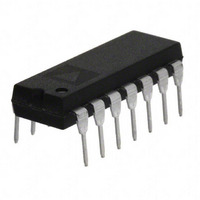
OP11EPZ Analog Devices Inc, OP11EPZ Datasheet - Page 3

OP11EPZ
Manufacturer Part Number
OP11EPZ
Description
IC OPAMP GP QUAD LN 14DIP
Manufacturer
Analog Devices Inc
Specifications of OP11EPZ
Slew Rate
1 V/µs
Amplifier Type
General Purpose
Number Of Circuits
4
Current - Input Bias
180nA
Voltage - Input Offset
300µV
Voltage - Supply, Single/dual (±)
±5 V ~ 15 V
Operating Temperature
0°C ~ 70°C
Mounting Type
Through Hole
Package / Case
14-DIP (0.300", 7.62mm)
Op Amp Type
Low Noise
No. Of Amplifiers
4
Bandwidth
3MHz
Supply Voltage Range
± 5V To ± 15V
Amplifier Case Style
DIP
No. Of Pins
14
Operating Temperature Range
0°C To +70°C
Channel Separation
130
Common Mode Rejection Ratio
120
Current, Input Bias
180 nA
Current, Input Offset
5.5 nA
Impedance, Thermal
39 °C/W
Number Of Amplifiers
Quad
Package Type
PDIP-14
Power Dissipation
105 mW
Resistance, Input
0.29 Megohms (Differential)
Temperature, Operating, Range
0 to +70 °C
Time, Rise
110 ns
Voltage, Gain
650 V/mV
Voltage, Input
±13 V
Voltage, Noise
18 nV/sqrt Hz
Voltage, Offset
0.3 mV
Voltage, Output, High
+13 V
Voltage, Output, Low
-13 V
Voltage, Supply
±15 V
Lead Free Status / RoHS Status
Lead free / RoHS Compliant
Current - Supply
-
Output Type
-
Current - Output / Channel
-
-3db Bandwidth
-
Gain Bandwidth Product
-
Lead Free Status / Rohs Status
RoHS Compliant part
Electrostatic Device
Available stocks
Company
Part Number
Manufacturer
Quantity
Price
Company:
Part Number:
OP11EPZ
Manufacturer:
ST
Quantity:
15 561
SPECIFICATIONS
ELECTRICAL CHARACTERISTICS
V
Table 1.
Parameter
Input Offset Voltage
Input Offset Current
Input Bias Current
Input Resistance Differential Mode
Input Voltage Range
Common-Mode Rejection Ratio
Power Supply Rejection Ratio
Output Voltage Swing
Large Signal Voltage Gain
Power Consumption
Input Noise Voltage
Input Noise Voltage Density
Input Noise Current
Input Noise Current Density
Channel Separation
Slew Rate
Large Signal Bandwidth
Closed-Loop Bandwidth
Rise Time
Overshoot
1
2
3
4
Guaranteed by input bias current.
Total dissipation for all four amplifiers in package.
Sample tested.
Guaranteed by rise time.
S
= ±15 V, T
3
3
3
A
= 25°C, unless otherwise noted.
2
3
4
1
Symbol
V
I
I
R
IVR
CMRR
PSRR
V
A
P
e
e
I
I
SR
BW
t
OS
CS
OS
B
n
n
f
d
n
n
OS
IN
O
VO
p-p
p-p
Rev. B | Page 3 of 12
Conditions
R
V
V
R
R
V
0.1 Hz to 10 Hz
f
f
f
0.1 Hz to 10 Hz
f
f
f
V
A
A
O
O
O
O
O
O
S
CM
S
L
L
O
O
VCL
V
= 10 Hz
= 100 Hz
= 1 kHz
= 10 Hz
= 100 Hz
= 1 kHz
≤ 10 kΩ
= ±5 V to ±15 V, R
= 2 kΩ
≤ 2 kΩ, V
= 0 V
= 20 V p-p
= 1, V
= ±12 V, R
= 1
IN
= 50 mV
O
= ±10 V
S
≤ 10 kΩ
S
≤ 10 kΩ
Min
0.17
±12
100
±11
100
100
0.7
11
2.4
Typ
0.3
5.5
180
0.29
±13
120
4
±13
650
105
0.7
18
14
12
17
1.8
1.5
1.2
130
1.0
16
3.0
110
15
Max
0.5
20
300
32
180
145
25
Unit
mV
nA
nA
MΩ
V
dB
μV/V
V
V/mV
mW
μV p-p
nV/√Hz
nV/√Hz
nV/√Hz
pA p-p
pA/√Hz
pA/√Hz
pA/√Hz
dB
V/μs
kHz
MHz
ns
%
OP11


