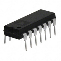
OP497GPZ Analog Devices Inc, OP497GPZ Datasheet - Page 12

OP497GPZ
Manufacturer Part Number
OP497GPZ
Description
IC OPAMP GP 500KHZ QUAD 14DIP
Manufacturer
Analog Devices Inc
Datasheet
1.OP497GPZ.pdf
(16 pages)
Specifications of OP497GPZ
Slew Rate
0.15 V/µs
Amplifier Type
General Purpose
Number Of Circuits
4
Gain Bandwidth Product
500kHz
Current - Input Bias
60pA
Voltage - Input Offset
80µV
Current - Supply
525µA
Current - Output / Channel
25mA
Voltage - Supply, Single/dual (±)
±2 V ~ 20 V
Operating Temperature
-40°C ~ 85°C
Mounting Type
Through Hole
Package / Case
14-DIP (0.300", 7.62mm)
Op Amp Type
Precision
No. Of Amplifiers
4
Bandwidth
500kHz
Supply Voltage Range
± 2V To ± 20V
Amplifier Case Style
DIP
No. Of Pins
14
Lead Free Status / RoHS Status
Lead free / RoHS Compliant
Output Type
-
-3db Bandwidth
-
Lead Free Status / RoHS Status
Lead free / RoHS Compliant, Lead free / RoHS Compliant
Available stocks
Company
Part Number
Manufacturer
Quantity
Price
OP497
APPLICATIONS CIRCUIT
PRECISION ABSOLUTE VALUE AMPLIFIER
The circuit in Figure 36 is a precision absolute value amplifier
with an input impedance of 30 MΩ. The high gain and low
TCV
input signals. In this circuit, the input always appears as a common-
mode signal to the op amps. The CMR of the OP497 exceeds
120 dB, yielding an error of less than 2 ppm.
PRECISION CURRENT PUMP
Maximum output current of the precision current pump shown
in Figure 37 is ±10 mA. Voltage compliance is ±10 V with ±15 V
supplies. Output impedance of the current transmitter exceeds
3 MΩ with linearity better than 16 bits.
V
IN
OS
2
3
I
of the OP497 ensure accurate operation with microvolt
OUT
OP497
V
+15V
–15V
1/4
IN
=
–
+
V
8
4
R5
0.1µF
IN
Figure 36. Precision Absolute Value Amplifier
C2
0.1µF
=
10kΩ
10kΩ
C3
100Ω
R1
R2
1
V
Figure 37. Precision Current Pump
IN
C1
30pF
=
10mA/V
2
3
10kΩ
R4
OP497
1N4148
D1
1N4148
10kΩ
1/4
R3
D2
1kΩ
R1
7
1
OP497
+15V
–15V
R2
2kΩ
1/4
8
4
6
5
10kΩ
OP497
R5
1kΩ
5
6
1/4
R3
0V < V
7
±10mA
I
OUT
OUT
< 10V
Rev. E | Page 12 of 16
PRECISION POSITIVE PEAK DETECTOR
In Figure 38, the C
polyethylene to minimize dielectric absorption and leakage.
The droop rate is determined by the size of C
current of the OP497.
SIMPLE BRIDGE CONDITIONING AMPLIFIER
Figure 39 shows a simple bridge conditioning amplifier using
the OP497. The transfer function is
The REF43 provides an accurate and stable reference voltage for
the bridge. To maintain the highest circuit accuracy, R
be 0.1% or better with a low temperature coefficient.
V
IN
V
Figure 39. Simple Bridge Conditioning Amplifier Using the OP497
OUT
1kΩ
REF43
+5V
=
2
4
2
3
V
OP497
REF
6
Figure 38. Precision Positive Peak Detector
1/4
2.5V
⎛
⎜
⎜
⎝
R
R
6
5
H
R
OP497
must be of polystyrene, Teflon®, or
RESET
Δ
V
+
1
REF
1/4
R
Δ
+5V
–5V
R
8
4
1N4148
R + ΔR
1kΩ
R
⎞
⎟
⎟
⎠
C
H
R
R
7
2N930
F
1kΩ
+
V
2
3
OUT
1kΩ
OP497
= V
1/4
6
5
R
REF
OP497
F
1/4
+15V
–15V
(
4
H
R + ΔR
1
8
0.1µF
0.1µF
ΔR
and the bias
7
)
V
OUT
R
R
F
F
should
V
OUT


