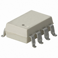
HCPL-7510-300E Avago Technologies US Inc., HCPL-7510-300E Datasheet - Page 5

HCPL-7510-300E
Manufacturer Part Number
HCPL-7510-300E
Description
OPTOCOUPLER CURR SENSE GW 8-SMD
Manufacturer
Avago Technologies US Inc.
Type
Miniature Isolation Amplifierr
Datasheet
1.HCPL-7510-000E.pdf
(17 pages)
Specifications of HCPL-7510-300E
Package / Case
8-SMD Gull Wing
Amplifier Type
Isolation
Number Of Circuits
1
-3db Bandwidth
100kHz
Current - Input Bias
600nA
Voltage - Input Offset
600µV
Current - Supply
11.7mA
Current - Output / Channel
16mA
Voltage - Supply, Single/dual (±)
4.5 V ~ 5.5 V
Operating Temperature
-40°C ~ 85°C
Mounting Type
Surface Mount
Common Mode Rejection Ratio (min)
63 dB
Mounting Style
SMD/SMT
Bandwidth
100 kHz
Input Offset Voltage
- 0.6 mV
Operating Supply Voltage
5.5 V
Supply Current
16 mA
Operating Temperature Range
- 40 C to + 85 C
No. Of Channels
1
Isolation Voltage
3.75kV
Optocoupler Output Type
Analog
Input Current
16mA
Output Voltage
6V
Opto Case Style
SMD
No. Of Pins
8
Common Mode Ratio
15000
Rohs Compliant
Yes
Lead Free Status / RoHS Status
Lead free / RoHS Compliant
Output Type
-
Slew Rate
-
Gain Bandwidth Product
-
Lead Free Status / Rohs Status
Lead free / RoHS Compliant
Other names
516-1683-5
Available stocks
Company
Part Number
Manufacturer
Quantity
Price
Company:
Part Number:
HCPL-7510-300E
Manufacturer:
AVAGO
Quantity:
7 500
Part Number:
HCPL-7510-300E
Manufacturer:
AVAGO/安华高
Quantity:
20 000
Regulatory Information
The HCPL-7510 has been approved by the following organizations:
IEC/EN/DIN EN 60747-5-2
Approved under:
IEC 60747-5-2:1997 + A1:2002
EN 60747-5-2:2001 + A1:2002
DIN EN 60747-5-2 (VDE 0884 Teil 2):2003-01.
IEC/EN/DIN EN 60747-5-2 Insulation Characteristics
Description
Installation classification per DIN EN 0110-1/1997-04, Table 1
Climatic Classification
Pollution Degree (DIN EN 0110-1/1997-04)
Maximum Working Insulation Voltage
Input to Output Test Voltage, Method b
Input to Output Test Voltage, Method a
Highest Allowable Overvoltage (transient overvoltage t
Safety-limiting values – maximum values allowed in the event of a failure.
Insulation Resistance at T
Notes:
1. Insulation characteristics are guaranteed only within the safety maximum ratings which
2. Refer to the optocoupler section of the Isolation and Control Components Designer’s Cata-
3. Refer to the following figure for dependence of P
5
V
V
for rated mains voltage
for rated mains voltage
for rated mains voltage
Case Temperature
Input Current
Output Power
must be ensured by protective circuits within the application. Surface Mount Classifications
is Class A in accordance with CECC00802.
log, under Product Safety Regulations section,
(IEC/EN/DIN EN 60747-5-2) for a detailed description of Method a and Method b partial dis-
charge test profiles.
IORM
IORM
x 1.875 = V
x 1.5 = V
[3]
[3]
PR
, type and sample test, t
PR
, 100% production test with t
S
≤
≤
≤
, V
150 V
300 V
600 V
IO
= 500 V
rms
rms
rms
[2]
[2]
m
= 60 sec, partial discharge <5 pC
S
and I
m
S
= 1 sec, partial discharge <5 pC
on ambient temperature.
ini
[1]
= 10 sec)
UL
Approved under UL 1577, component recognition
program up to V
CSA
Approved under CSA Component Acceptance Notice #5,
File CA 88324.
ISO
= 3750 V
800
700
600
500
400
300
200
100
Symbol
V
V
V
V
T
I
P
R
0
S, INPUT
S
IORM
PR
PR
IOTM
S, OUTPUT
S
0
RMS
25
T
S
. File E55361.
– CASE TEMPERATURE – °C
50 75 100
Characteristic Unit
I – IV
I – III
I – II
55/100/21
2
891
1670
1336
6000
175
400
600
>10
9
125
P
I
150 175
S
S
(mA)
(mW)
V
V
V
V
°C
mA
mW
Ω
peak
peak
peak
peak
200


