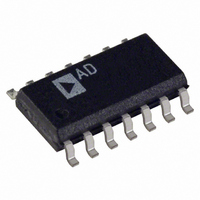
OP496GSZ Analog Devices Inc, OP496GSZ Datasheet - Page 15

OP496GSZ
Manufacturer Part Number
OP496GSZ
Description
IC OPAMP GP R-R 450KHZ LP 14SOIC
Manufacturer
Analog Devices Inc
Specifications of OP496GSZ
Slew Rate
0.3 V/µs
Amplifier Type
General Purpose
Number Of Circuits
4
Output Type
Rail-to-Rail
Gain Bandwidth Product
450kHz
Current - Input Bias
10nA
Voltage - Input Offset
35µV
Current - Supply
60µA
Current - Output / Channel
4mA
Voltage - Supply, Single/dual (±)
3 V ~ 12 V, ±1.5 V ~ 6 V
Operating Temperature
-40°C ~ 125°C
Mounting Type
Surface Mount
Package / Case
14-SOIC (3.9mm Width), 14-SOL
Op Amp Type
General Purpose
No. Of Amplifiers
4
Bandwidth
450kHz
Supply Voltage Range
3V To 12V
Amplifier Case Style
SOIC
No. Of Pins
14
Common Mode Rejection Ratio
65
Current, Input Bias
±10 nA
Current, Input Offset
±1.5 nA
Current, Output
±4 mA
Current, Supply
60 μA
Impedance, Thermal
43 °C/W
Number Of Amplifiers
Quad
Package Type
SOIC-8
Temperature, Operating, Range
-40 to +125 °C
Voltage, Gain
200 V/mV
Voltage, Input
5 V (Common-Mode)
Voltage, Noise
26 nV/sqrt Hz
Voltage, Offset
35 μV
Voltage, Output, High
4.56 V
Voltage, Output, Low
350 mV
Voltage, Supply
5 V
Lead Free Status / RoHS Status
Lead free / RoHS Compliant
-3db Bandwidth
-
Lead Free Status / Rohs Status
RoHS Compliant part
Electrostatic Device
Available stocks
Company
Part Number
Manufacturer
Quantity
Price
Part Number:
OP496GSZ
Manufacturer:
ADI/亚德诺
Quantity:
20 000
.SUBCKT OP496
IREF 21
QB1
QB2
QB3
QB4
QB5
Q1
Q2
Q3
Q4
Q5
Q6
EOS
Q7
Q8
Q9
Q10
Q11
Q12
R1
R2
R3
R4
IOS
C10
C11
AD589
OP496 SPICE Macro-model
Copyright 1995 by Analog Devices, Inc.
Refer to “README.DOC” file for License Statement.
Use of this model indicates your acceptance of the
terms and provisions in the License Statement.
INPUT STAGE
Node assignments
100
2.55M
6.17k
RTD
26.7k
D
21
22
4
22
11
5
6
4
4
50
50
3
99
99
12
13
11
11
99
99
12
13
1
5
12
5V
10-TURNS
37.4k
200
50
21
21
21
22
22
4
4
4
4
1
3
2
1
3
11
11
11
11
5
6
50
50
2
6
13
26.7k
100
A1
1/4
OP496
Noninverting input
1
1U
99
99
99
50
50
7
8
7
8
7
8
POLY(1)
9
10
9
10
9
10
50K
50K
50K
50K
0.75N
3.183P
3.183P
100k
NOTE:
ALL RESISTORS 1% OR BETTER
Inverting input
2
99
99
99
50
50
50
50
50
50
99
99
50
50
99
99
99
99
A2
1/4
OP496
392
20k
REV. C, 5/95
ARG / ADSC
Positive supply
99
QP
QP
QP
QN
QN
QN
QN
QN
QN
QP
QP
(17,98) 35U 1
QN
QN
QP
QP
QP
QP
392
GAIN = 259
Negative supply
50
1
1
1.5
2
3
2
2
1
1
2
2
2
2
2
2
1
1
A3
100k
0.1 F
5V
1/4
OP496
Output
49
V
OUT
Amplifiers A2 and A3 are configured in a two op amp instru-
mentation amplifier configuration. For ease of measurement,
the IA resistors are chosen to produce a gain of 259, so that
each 1°C increase in temperature results in a 10 mV increase in
the output voltage. To reduce measurement noise, the band-
width of the amplifier is limited. A 0.1 µF capacitor, connected
in parallel with the 100 kΩ resistor on amplifier A3, creates a
pole at 16 Hz.
CIN
EREF 98
G1
R10
CC
D1
D2
ECM 16
R11
R12
ISY
EIN
Q24
QD4
Q27
R5
R6
Q26
QD5
Q28
QL1
R7
I4
QD7
QD6
Q29
Q30
QD10 45
R9
Q31
QD8
QD9
R8
I5
Q32
Q33
.MODEL
.MODEL
.MODEL
.ENDS
GAIN STAGE
COMMON-MODE STAGE
OUTPUT STAGE
1
98
15
15
15
50
16
17
99
35
37
37
40
36
99
39
40
41
37
99
99
42
43
47
44
45
46
47
48
99
99
49
49
0
15
98
49
99
15
98
17
98
50
50
35
37
37
39
38
42
40
40
41
41
43
42
43
43
45
46
46
47
47
48
51
46
48
44
DX D()
QN NPN(BF=120VAF=100)
QP
2
POLY(2)
POLY(2)
251.641MEG
8P
DX
DX
POLY(2)
1MEG
10
20U
POLY(1)
36
38
38
150K
45K
50
39
44
99
10.7K
2U
50
42
44
50
50
175
48
48
51
2.9K
1U
99
50
PNP(BF=80 VAF=60)
1P
OP196/OP296/OP496
50
99
99
50
50
50
99
50
50
50
50
50
99
99
99
99
50
(99,0)
(6,5)
(1,98)
(15,98) 1.42735 1
QN
QP
QP
QN
QN
QN
QP
QN
QN
QN
QN
QN
QP
QP
QP
QP
QN
(50,0) 0 0.5 0.5
(13,12) 0 10U 10U
(2,98) 0 0.5 0.5
1
1
1
3
1
1
1
2
2
1
1.5
1
1
1
5
10
4


