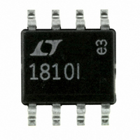
LT1810IS8#PBF Linear Technology, LT1810IS8#PBF Datasheet - Page 20

LT1810IS8#PBF
Manufacturer Part Number
LT1810IS8#PBF
Description
IC OPAMP R-R I/O DUAL 8-SOIC
Manufacturer
Linear Technology
Datasheet
1.LT1809CS6TRMPBF.pdf
(24 pages)
Specifications of LT1810IS8#PBF
Amplifier Type
General Purpose
Number Of Circuits
2
Output Type
Rail-to-Rail
Slew Rate
350 V/µs
Gain Bandwidth Product
180MHz
-3db Bandwidth
320MHz
Current - Input Bias
12.5µA
Voltage - Input Offset
800µV
Current - Supply
15mA
Current - Output / Channel
85mA
Voltage - Supply, Single/dual (±)
2.5 V ~ 12.6 V, ±1.25 V ~ 6.3 V
Operating Temperature
-40°C ~ 85°C
Mounting Type
Surface Mount
Package / Case
8-SOIC (3.9mm Width)
Lead Free Status / RoHS Status
Lead free / RoHS Compliant
Available stocks
Company
Part Number
Manufacturer
Quantity
Price
LT1809/LT1810
TYPICAL APPLICATIONS
Single Supply Video Line Driver
The LT1809 is a wideband rail-to-rail op amp with a large
output current that allows it to drive video signals in low
supply applications. Figure 8 depicts a single supply
video line driver with AC coupling to minimize the qui-
escent power dissipation. Resistors R1 and R2 are used
to level-shift the input and output to provide the largest
signal swing. A gain of 2 is set up with R3 and R4 to re-
store the signal at V
to the matching of the 75Ω line with the back-terminated
20
V
ON 2.5V DC
IN
1V
V
P-P
R
75Ω
IN
T
33μF
Figure 8. 5V Single Supply Video Line Driver
C1
1k
3
2
0.15μF
Figure 6. Single Supply A/D Driver
+
–
R1
5k
R2
5k
LT1809
+
5V
3
2
R3
1k
7
4
C2
150μF
OUT
–
+
LT1809
1
1k
, which is attenuated by 6dB due
5V
6
7
4
470pF
49.9Ω
3pF
R4
C4
1k
6
1000μF
C3
1
2
+A
–A
IN
75Ω
1μF
IN
R5
V
PGA GAIN = 2
REF = 4.096V
CM
3
LTC1420
5V
COAX CABLE
75Ω
1809 F06
•
•
•
resistor, R5. The back termination will eliminate any re-
fl ection of the signal that comes from the load. The input
termination resistor, R
matching of the incoming line is necessary. The values of
C1, C2 and C3 are selected to minimize the droop of the
luminance signal. In some less stringent requirements, the
value of capacitors could be reduced. The – 3dB bandwidth
of the driver is about 95MHz on 5V supply and the amount
of peaking will vary upon the value of capacitor C4.
12 BITS
10Msps
R
75Ω
1809 F08
LOAD
V
OUT
Figure 9. Video Line Driver Frequency Response
–100
–120
–20
–40
–60
–80
–1
–2
–3
–4
–5
0
5
4
3
2
1
0
0.2
Figure 7. 4096 Point FFT Response
0
V
S
= 5V
1
1
T
, is optional—it is used only if
FREQUENCY (MHz)
FREQUENCY (MHz)
2
10
3
V
A
f
f
SFDR = 80dB
SAMPLE
IN
S
V
= 5V
= +2
= 1.394MHz
= 10Msps
4
100
1809 F07
1809 F09
5
180910fa


