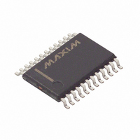
MAXQ3210-EJX+ Maxim Integrated Products, MAXQ3210-EJX+ Datasheet - Page 7

MAXQ3210-EJX+
Manufacturer Part Number
MAXQ3210-EJX+
Description
IC MCU 16BIT LP 24-TSSOP
Manufacturer
Maxim Integrated Products
Series
MAXQ™r
Datasheet
1.MAXQ3210-EJX.pdf
(28 pages)
Specifications of MAXQ3210-EJX+
Core Processor
RISC
Core Size
16-Bit
Speed
3.6MHz
Peripherals
LED, Power-Fail Reset, POR, PWM, WDT
Number Of I /o
15
Program Memory Size
2KB (1K x 16)
Program Memory Type
EEPROM
Eeprom Size
128 x 8
Ram Size
64 x 8
Voltage - Supply (vcc/vdd)
4.5 V ~ 5.5 V
Oscillator Type
Internal
Operating Temperature
-40°C ~ 85°C
Package / Case
24-TSSOP
Processor Series
MAXQ3210
Core
RISC
Data Bus Width
16 bit
Data Ram Size
64 B
Interface Type
JTAG
Maximum Clock Frequency
3.58 mhZ
Number Of Programmable I/os
15
Number Of Timers
1
Operating Supply Voltage
6 V to 9.5 V
Maximum Operating Temperature
+ 85 C
Mounting Style
SMD/SMT
Development Tools By Supplier
MAXQ3210-KIT
Minimum Operating Temperature
- 40 C
Lead Free Status / RoHS Status
Lead free / RoHS Compliant
Data Converters
-
Connectivity
-
Lead Free Status / Rohs Status
Details
PIN
13
14
15
16
17
18
19
20
21
22
23
24
Microcontroller with Internal Voltage Regulator,
RESET/P1.1
GND
CMPI/P0.5
TMS/P1.2
REGOUT
LED/P0.7
TDI/P1.0
INT/P0.6
HORNB
HORNS
NAME
FEED
V
DD
HORN
Piezoelectric Horn Driver, and Comparator
Piezoelectric Horn Driver, Feedback. This input is connected to the feedback electrode of the horn. If FEED is
not used, it should be grounded.
Piezoelectric Horn Driver, Horn Brass. This output pin is connected to the piezo metal support electrode of the
horn.
Piezoelectric Horn Driver, Ground. This pin should be connected to GND, the same ground as pin 1. There is
no special isolation required for this pin.
Piezoelectric Horn Driver, Horn Silver. This output pin is connected to the ceramic electrode and provides the
complementary output to HORNB when the horn output is enabled.
Digital Power. This pin should be connected to a bypass capacitor to ground.
Voltage Regulator Output. This pin provides the regulated output of the internal voltage regulator. This pin
requires sufficient bypass capacitance, preferrably a parallel combination of 10µF and 0.1µF capacitors
between this pin and ground.
D e b u g Po r t Sig n a l T M S o r G e n e r a l- Pu r p o s e , D i g it a l I/ O , Ty p e D Po r t . Thi s p i n functi ons as ei ther the TM S
si g nal of the d eb ug p or t or as a b i d i r ecti onal I/O . The p i n d efaul ts to a d i g i tal i np ut w i th a w eak p ul l up after a r eset.
Active-Low Reset Input or General-Purpose, Digital I/O, Type D Port. This pin defaults to the reset input
mode of operation following a POR. The reset input mode can be deactivated and the digital I/O mode enabled
by programming the RSTD bit to 1.
D e b u g Po r t Sig n a l T D I o r G e n e r a l- Pu r p o s e , D i g it a l I/ O , Ty p e D Po r t . Thi s p i n functi ons as ei ther the TD I si g nal
of the d eb ug p or t or as a b i d i r ecti onal I/O . The p i n d efaul ts to a d i g i tal i np ut w i th a w eak p ul l up after a r eset.
High-Current (Sink) Driver Output or General-Purpose, Digital I/O, Type D Port. This pin functions with a
high-current pulldown to drive a device such as an LED or as a bidirectional I/O. The pin defaults to a digital
input with a weak pullup after a reset.
External Edge-Selectable Interrupt or General-Purpose, Digital I/O, Type D Port. This pin functions as either
an external edge-selectable interrupt or as a bidirectional I/O. The pin defaults to a digital input with a weak
pullup after a reset.
Analog Voltage Comparator Input or General-Purpose, Digital I/O, Type D Port. This pin functions as either
the input to the analog voltage comparator or as a bidirectional I/O. The pin defaults to a digital input with a weak
pullup after a reset.
_____________________________________________________________________
FUNCTION
Pin Description (continued)
7


