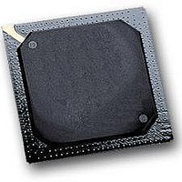
MPC5553MZP132 Freescale Semiconductor, MPC5553MZP132 Datasheet - Page 62

MPC5553MZP132
Manufacturer Part Number
MPC5553MZP132
Description
IC MCU MPC5553 REV A 416-PBGA
Manufacturer
Freescale Semiconductor
Series
MPC55xx Qorivvar
Datasheet
1.MPC5553EVBE.pdf
(68 pages)
Specifications of MPC5553MZP132
Core Processor
e200z6
Core Size
32-Bit
Speed
132MHz
Connectivity
CAN, EBI/EMI, Ethernet, SCI, SPI
Peripherals
DMA, POR, PWM, WDT
Number Of I /o
220
Program Memory Size
1.5MB (1.5M x 8)
Program Memory Type
FLASH
Ram Size
64K x 8
Voltage - Supply (vcc/vdd)
1.35 V ~ 1.65 V
Data Converters
A/D 40x12b
Oscillator Type
External
Operating Temperature
-40°C ~ 125°C
Package / Case
416-PBGA
Processor Series
MPC5xxx
Core
e200z6
Data Bus Width
32 bit
Data Ram Size
64 KB
Interface Type
7-Wire, DSPI, ESCI
Maximum Clock Frequency
132 MHz
Number Of Timers
56
Maximum Operating Temperature
+ 125 C
Mounting Style
SMD/SMT
Minimum Operating Temperature
- 40 C
For Use With
MPC5553EVBISYS - KIT EVAL ISYSTEMS MPC5553MPC5553EVBGHS - KIT EVAL GREEN HILLS SOFTWAREMPC5553EVB - KIT EVAL MPC5553MZP132MPC5553EVBE - BOARD EVAL FOR MPC5553
Lead Free Status / RoHS Status
Lead free / RoHS Compliant
Eeprom Size
-
Lead Free Status / Rohs Status
No
Available stocks
Company
Part Number
Manufacturer
Quantity
Price
Company:
Part Number:
MPC5553MZP132
Manufacturer:
Freescale Semiconductor
Quantity:
10 000
Revision History for the MPC5553 Data Sheet
The following table describes the changes made to information in tables and figures, and is presented in
sequential page number order.
62
Figure 1
Table 1
Table 2
Table 4
Table 5
Table
Location
6, VCR/POR Electrical Specifications:
Orderable Part Numbers:
EMI Testing Specifications: Changed the maximum operating frequency to from 132 to f
ESD Characteristics: Added (Electromagnetic Static Discharge) in the section title.
Absolute Maximum Ratings:
MPC5500 Family Part Numbers:
• Removed the 2 in the tape and reel designator in both the graphic and in the Tape and Reel Status text.
• Changed Qualification Status by adding ‘, general market flow’ to the M designator, and added an ‘S’ designator
• Moved the ‘Lead-free’ or ‘Lead’ in the Package Description column to a second line and added ‘Pb-free’ and
• Footnote 2 changed to read:’ The lowest ambient operating temperature is referenced by T
• Footnote 3 changed to read: ‘Speed is the nominal maximum frequency. Max speed is the maximum speed
• Deleted Spec 3, “Flash core voltage.”
• Spec 21, Added the name of the spec, ‘V
• Spec 28 “Maximum Solder Temperature”: Added two lines:
• Footnote 1, added: ‘any of’ between ‘beyond’ and ‘the listed maxima.’
• Deleted footnote 2: ‘Absolute maximum voltages are currently maximum burn-in voltages. Absolute maximum
• Footnote 6 (now footnote 5): Changed to the following sentence to the end, “Internal structures hold the input
• Subscript all symbol names that appear after the first underscore character.
• Removed ‘Tj ‘ after ‘150 C’ in the last line, second column: Characteristic.
• Reformatted columns.
• Added footnote 1 to specs 1, 2, and 3 that reads: On power up, assert RESET before V
• Added to Spec 2:
• Specs 7 and 10: added ‘at Tj ‘ at the end of the first line in the second column: Characteristic.
• Spec 10:
• Added a new footnote 7, ‘Refer to
• Rewrote old footnote 8 (new footnote 9) to read: Represents the worst-case external transistor BETA. It is
• Deleted old footnote 9: ‘Preliminary value. Final specification pending characterization.’
with the description of ‘Fully spec. qualified, automotive flow.
‘SnPb’ respectively. Changed Lead to Leaded.
operating temperature is referenced by T
allowed including frequency modulation (FM): 82 MHz parts allow for 80 MHz system clock + 2% FM; 114 MHz
parts allow for 112 MHz system clock + 2% FM; and 132 MHz parts allow for 128 MHz system clock + 2% FM;.’
reference to
Lead-free (Pb-free) and Leaded (SnPb) with maximum values of 260 C and 245 C respectively.
specifications for device stress have not yet been determined.’
voltage greater than -1.0 V if the injection current limit of 2 mA is met. Keep the negative DC voltage greater than
-0.6 V on eTPU[15] and on SINB during the internal power-on reset (POR) state.”
negate (internal POR). RESET must remain asserted until the power supplies are within the operating conditions
as specified in
fall outside the operating conditions and until the internal POR asserts.
measured on a per-part basis and calculated as (I
3.3 V (V
3.3 V (V
• Changed the minimum values of: -40 C = 40; 25 C = 45; 150 C = 55.
• Added cross-reference to footnote 6: ‘I
V
RC33
DDSYN
DDSYN
= 3.1 V, V
Table 33. Table and Figure Changes Between Rev. 2.0 and 3.0
Table
) POR negated (ramp down)
) POR asserted (ramp up)
Table 9
9, DC Electrical Specifications, to which the Spec was moved.
VRCCTL
DC Electrical Specifications. On power down, assert RESET before any power supplies
MPC5553 Microcontroller Data Sheet, Rev. 3.0
= 2.2 V.’ Changed ‘(@ V
Table 1
H
RC33
VRCCTL
Description of Changes
.’
for the maximum operating frequency.’
to V
is measured at the following conditions: V
DD
DDSYN
DD
Min. 0.0
÷
= 1.35 V, f
Min. 0.0
I
VRCCTL
differential voltage,’ as well as the name and cross
).
sys
Max 0.30
= f
Max 0.30
MAX
)‘ to ‘(@ f
V
V
MAX
sys
.
POR15
Freescale Semiconductor
= f
MAX
L
; the highest ambient
, V
DD
).
POR33
= 1.35 V,
, and V
POR5


