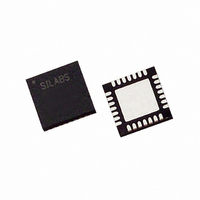
C8051F311 Silicon Laboratories Inc, C8051F311 Datasheet - Page 3

C8051F311
Manufacturer Part Number
C8051F311
Description
IC 8051 MCU 16K FLASH 28MLP
Manufacturer
Silicon Laboratories Inc
Series
C8051F31xr
Specifications of C8051F311
Core Processor
8051
Core Size
8-Bit
Speed
25MHz
Connectivity
SMBus (2-Wire/I²C), SPI, UART/USART
Peripherals
POR, PWM, Temp Sensor, WDT
Number Of I /o
25
Program Memory Size
16KB (16K x 8)
Program Memory Type
FLASH
Ram Size
1.25K x 8
Voltage - Supply (vcc/vdd)
2.7 V ~ 3.6 V
Data Converters
A/D 17x10b
Oscillator Type
Internal
Operating Temperature
-40°C ~ 85°C
Package / Case
28-VQFN Exposed Pad, 28-HVQFN, 28-SQFN, 28-DHVQFN
Lead Free Status / RoHS Status
Contains lead / RoHS non-compliant
Eeprom Size
-
Available stocks
Company
Part Number
Manufacturer
Quantity
Price
Part Number:
C8051F311-GM
Manufacturer:
SILICONLABS/芯科
Quantity:
20 000
Part Number:
C8051F311-GMR
Manufacturer:
SILICON LABS/芯科
Quantity:
20 000
Table Of Contents
1. System Overview.................................................................................................... 17
2. Absolute Maximum Ratings .................................................................................. 35
3. Global DC Electrical Characteristics .................................................................... 36
4. Pinout and Package Definitions............................................................................ 39
5. 10-Bit ADC (ADC0, C8051F310/1/2/3/6 only) ........................................................ 51
6. Voltage Reference (C8051F310/1/2/3/6 only)........................................................ 67
7. Comparators ........................................................................................................... 69
8. CIP-51 Microcontroller .......................................................................................... 79
1.1. CIP-51™ Microcontroller Core.......................................................................... 27
1.2. On-Chip Memory............................................................................................... 29
1.3. On-Chip Debug Circuitry................................................................................... 30
1.4. Programmable Digital I/O and Crossbar ........................................................... 31
1.5. Serial Ports ....................................................................................................... 32
1.6. Programmable Counter Array ........................................................................... 32
1.7. 10-Bit Analog to Digital Converter..................................................................... 33
1.8. Comparators ..................................................................................................... 34
5.1. Analog Multiplexer ............................................................................................ 51
5.2. Temperature Sensor ......................................................................................... 52
5.3. Modes of Operation .......................................................................................... 54
5.4. Programmable Window Detector ...................................................................... 61
8.1. Instruction Set ................................................................................................... 80
8.2. Memory Organization........................................................................................ 85
8.3. Interrupt Handler ............................................................................................... 93
1.1.1. Fully 8051 Compatible.............................................................................. 27
1.1.2. Improved Throughput ............................................................................... 27
1.1.3. Additional Features .................................................................................. 28
5.3.1. Starting a Conversion............................................................................... 54
5.3.2. Tracking Modes........................................................................................ 55
5.3.3. Settling Time Requirements ..................................................................... 56
5.4.1. Window Detector In Single-Ended Mode ................................................. 63
5.4.2. Window Detector In Differential Mode...................................................... 64
8.1.1. Instruction and CPU Timing ..................................................................... 80
8.1.2. MOVX Instruction and Program Memory ................................................. 81
8.2.1. Program Memory...................................................................................... 85
8.2.2. Data Memory............................................................................................ 86
8.2.3. General Purpose Registers ...................................................................... 86
8.2.4. Bit Addressable Locations........................................................................ 86
8.2.5. Stack ....................................................................................................... 86
8.2.6. Special Function Registers....................................................................... 87
8.2.7. Register Descriptions ............................................................................... 90
8.3.1. MCU Interrupt Sources and Vectors ........................................................ 94
8.3.2. External Interrupts .................................................................................... 95
8.3.3. Interrupt Priorities ..................................................................................... 95
Rev. 1.7
C8051F310/1/2/3/4/5/6/7
3


