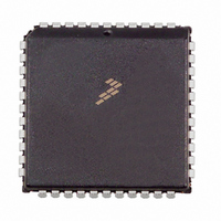
MC68HC711D3CFN2 Freescale Semiconductor, MC68HC711D3CFN2 Datasheet - Page 49

MC68HC711D3CFN2
Manufacturer Part Number
MC68HC711D3CFN2
Description
IC MCU 2MHZ 4K OTP 44-PLCC
Manufacturer
Freescale Semiconductor
Series
HC11r
Specifications of MC68HC711D3CFN2
Core Processor
HC11
Core Size
8-Bit
Speed
2MHz
Connectivity
SCI, SPI
Peripherals
POR, WDT
Number Of I /o
26
Program Memory Size
4KB (4K x 8)
Program Memory Type
OTP
Ram Size
192 x 8
Voltage - Supply (vcc/vdd)
4.5 V ~ 5.5 V
Oscillator Type
Internal
Operating Temperature
-40°C ~ 85°C
Package / Case
44-PLCC
Lead Free Status / RoHS Status
Contains lead / RoHS non-compliant
Eeprom Size
-
Data Converters
-
Available stocks
Company
Part Number
Manufacturer
Quantity
Price
Company:
Part Number:
MC68HC711D3CFN2
Manufacturer:
DIODES
Quantity:
12 000
Company:
Part Number:
MC68HC711D3CFN2
Manufacturer:
MOT
Quantity:
5 510
Company:
Part Number:
MC68HC711D3CFN2
Manufacturer:
Freescale Semiconductor
Quantity:
10 000
Bits 7, 6, and 2 — Not implemented
IRQE — IRQ Edge/Level Sensitivity Select
DLY — Stop Mode Exit Turnon Delay
CME — Clock Monitor Enable
CR1 and CR0 — COP Timer Rate Selects
4.3 Interrupts
Excluding reset-type interrupts, there are 17 hardware interrupts and one software interrupt that can be
generated from all the possible sources. These interrupts can be divided into two categories: maskable
and non-maskable. Fifteen of the interrupts can be masked using the I bit of the condition code register
(CCR). All the on-chip (hardware) interrupts are individually maskable by local control bits. The software
interrupt is non-maskable. The external input to the XIRQ pin is considered a non-maskable interrupt
because it cannot be masked by software once it is enabled. However, it is masked during reset and upon
receipt of an interrupt at the XIRQ pin. Illegal opcode is also a non-maskable interrupt.
Freescale Semiconductor
Always read 0.
This bit can be written only once during the first 64 E-clock cycles after reset in normal modes.
This bit is set during reset and can be written only once during the first 64 E-clock cycles after reset in
normal modes. If an external clock source rather than a crystal is used, the stabilization delay can be
inhibited because the clock source is assumed to be stable.
The COP system is driven by a constant frequency of E ÷ 2
divide-by value to arrive at the COP timeout rate. These bits are cleared during reset and can be written
only once during the first 64 E-clock cycles after reset in normal modes. The value of these bits is:
1 = IRQ is configured to respond only to falling edges.
0 = IRQ is configured for low-level wired-OR operation.
1 = A stabilization delay of 4064 E-clock cycles is imposed before processing resumes after a stop
0 = No stabilization delay is imposed after story recovery.
1 = Clock monitor circuit is enabled.
0 = Clock monitor circuit is disabled.
mode wakeup.
Address:
Reset:
Read:
Write:
Figure 4-2. System Configuration Options Register (OPTION)
$0039
Bit 7
0
0
CR1
0
0
1
1
6
0
0
MC68HC711D3 Data Sheet, Rev. 2.1
IRQE
5
0
CR0
0
1
0
1
DLY
4
1
CME
3
0
Divided By
E ÷ 2
15
16
64
. These two bits specify an additional
1
4
15
2
0
0
CR1
1
0
CR0
Bit 0
0
Interrupts
49


