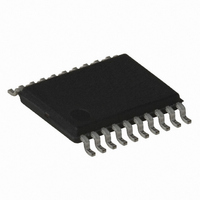
AT89LP2052-16XI Atmel, AT89LP2052-16XI Datasheet - Page 48

AT89LP2052-16XI
Manufacturer Part Number
AT89LP2052-16XI
Description
IC 8051 MCU FLASH 2K 20TSSOP
Manufacturer
Atmel
Series
89LPr
Datasheet
1.AT89LP2052-20PU.pdf
(94 pages)
Specifications of AT89LP2052-16XI
Core Processor
8051
Core Size
8-Bit
Speed
16MHz
Connectivity
SPI, UART/USART
Peripherals
Brown-out Detect/Reset, POR, PWM, WDT
Number Of I /o
15
Program Memory Size
2KB (2K x 8)
Program Memory Type
FLASH
Ram Size
256 x 8
Voltage - Supply (vcc/vdd)
2.4 V ~ 5.5 V
Oscillator Type
Internal
Operating Temperature
-40°C ~ 85°C
Package / Case
20-TSSOP
Lead Free Status / RoHS Status
Contains lead / RoHS non-compliant
Eeprom Size
-
Data Converters
-
Other names
AT89LP2052-20XI
AT89LP2052-20XI
AT89LP2052-20XI
Figure 19-4. SPI Transfer Format with CPHA = 0
Note:
Figure 19-5. SPI Transfer Format with CPHA = 1
Note:
19.4
48
*Not defined but normally MSB of character just received
*Not defined but normally LSB of previously transmitted character
SPI Pin Configuration
(FOR REFERENCE)
AT89LP2052/LP4052
(FROM MASTER)
SCK (CPOL = 0)
SCK (CPOL = 1)
SS (TO SLAVE)
(FROM SLAVE)
SCK CYCLE #
MOSI
MISO
Before using the Serial Peripheral Interface the four SPI pins – SCK, MISO, MOSI and SS –
must be properly configured for the desired functionality. See
tions” on page
bidirectional or output, with P1.7 and P1.5 set to “1”. MISO should be input-only, or bidirectional
with P1.6 set to “1”. When the SPI is in Slave mode, SCK, MOSI and SS must be configured as
input-only, or as bidirectional with P1.7, P1.6 and P1.4 set to “1”. MISO should be set as bidirec-
tional or output, with P1.6 set to “1”. If all four pins are set as bidirectional and their respectively
port bits are all “1”, it is possible to switch between Master and Slave mode without reconfiguring
the pins.
*
MSB
MSB
1
23. When the SPI is in Master mode, SCK and MOSI must be configured as
2
6
6
3
5
5
4
4
4
5
3
3
6
2
2
Section 15.7 “Port Alternate Func-
7
1
1
8
LSB
LSB
3547J–MICRO–10/09


