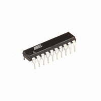
AT89LP2052-16PU Atmel, AT89LP2052-16PU Datasheet - Page 62

AT89LP2052-16PU
Manufacturer Part Number
AT89LP2052-16PU
Description
IC 8051 MCU FLASH 2K 20DIP
Manufacturer
Atmel
Series
89LPr
Specifications of AT89LP2052-16PU
Core Processor
8051
Core Size
8-Bit
Speed
16MHz
Connectivity
SPI, UART/USART
Peripherals
Brown-out Detect/Reset, POR, PWM, WDT
Number Of I /o
15
Program Memory Size
2KB (2K x 8)
Program Memory Type
FLASH
Ram Size
256 x 8
Voltage - Supply (vcc/vdd)
2.4 V ~ 5.5 V
Oscillator Type
Internal
Operating Temperature
-40°C ~ 85°C
Package / Case
20-DIP (0.300", 7.62mm)
Lead Free Status / RoHS Status
Lead free / RoHS Compliant
Eeprom Size
-
Data Converters
-
- Current page: 62 of 94
- Download datasheet (2Mb)
23.4.3
23.4.4
62
AT89LP2052/LP4052
Program Enable
Chip Erase
Function:
Usage:
Figure 23-7. Program Enable Sequence
Function:
Usage:
Figure 23-8. Chip Erase Sequence
Note:
• Enables the programming interface to receive commands.
• Program Enable must be the first command issued in any programming session. In parallel
1. Bring CS (P3.2) low.
2. Drive P1 to AAh and pulse XTAL1 high.
3. Drive P1 to ACh and pulse XTAL1 high.
4. Drive P1 to 53h and pulse XTAL1 high.
5. Bring CS high.
• Erases (programs FFh to) the entire 2/4-Kbyte memory array.
• Erases User Signature Row if User Row Programming Fuse bit is enabled.
• Lockbit1 and Lockbit2 are programmed to “unlock” state.
1. Bring CS (P3.2) low.
2. Drive P1 to AAh and pulse XTAL1 high.
3. Drive P1 to 8Ah and pulse XTAL1 high.
4. Bring CS high.
5. Wait 4 ms, monitor P3.1, or poll data/status.
programming a session is active while RST remains at V
is active while RST remains at V
RDY/BSY
XTAL1
XTAL1
The waveforms on this page are not to scale.
CS
P1
CS
P1
AAh
AAh
CC
ACh
.
8Ah
53h
PP
. In serial programming a session
3547J–MICRO–10/09
Related parts for AT89LP2052-16PU
Image
Part Number
Description
Manufacturer
Datasheet
Request
R

Part Number:
Description:
DEV KIT FOR AVR/AVR32
Manufacturer:
Atmel
Datasheet:

Part Number:
Description:
INTERVAL AND WIPE/WASH WIPER CONTROL IC WITH DELAY
Manufacturer:
ATMEL Corporation
Datasheet:

Part Number:
Description:
Low-Voltage Voice-Switched IC for Hands-Free Operation
Manufacturer:
ATMEL Corporation
Datasheet:

Part Number:
Description:
MONOLITHIC INTEGRATED FEATUREPHONE CIRCUIT
Manufacturer:
ATMEL Corporation
Datasheet:

Part Number:
Description:
AM-FM Receiver IC U4255BM-M
Manufacturer:
ATMEL Corporation
Datasheet:

Part Number:
Description:
Monolithic Integrated Feature Phone Circuit
Manufacturer:
ATMEL Corporation
Datasheet:

Part Number:
Description:
Multistandard Video-IF and Quasi Parallel Sound Processing
Manufacturer:
ATMEL Corporation
Datasheet:

Part Number:
Description:
High-performance EE PLD
Manufacturer:
ATMEL Corporation
Datasheet:

Part Number:
Description:
8-bit Flash Microcontroller
Manufacturer:
ATMEL Corporation
Datasheet:

Part Number:
Description:
2-Wire Serial EEPROM
Manufacturer:
ATMEL Corporation
Datasheet:


