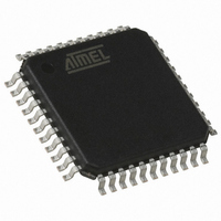
T89C51CC01CA-RLTIM Atmel, T89C51CC01CA-RLTIM Datasheet - Page 11

T89C51CC01CA-RLTIM
Manufacturer Part Number
T89C51CC01CA-RLTIM
Description
IC 8051 MCU FLASH 32K 44VQFP
Manufacturer
Atmel
Series
AT89C CANr
Datasheets
1.T89C51CC01CA-7CTIM.pdf
(167 pages)
2.T89C51CC01CA-7CTIM.pdf
(12 pages)
3.T89C51CC01CA-7CTIM.pdf
(32 pages)
4.T89C51CC01CA-7CTIM.pdf
(29 pages)
Specifications of T89C51CC01CA-RLTIM
Core Processor
8051
Core Size
8-Bit
Speed
40MHz
Connectivity
CAN, UART/USART
Peripherals
POR, PWM, WDT
Number Of I /o
32
Program Memory Size
32KB (32K x 8)
Program Memory Type
FLASH
Eeprom Size
2K x 8
Ram Size
1.25K x 8
Voltage - Supply (vcc/vdd)
3 V ~ 5.5 V
Data Converters
A/D 8x10b
Oscillator Type
External
Operating Temperature
-40°C ~ 85°C
Package / Case
44-TQFP, 44-VQFP
For Use With
AT89STK-06 - KIT DEMOBOARD 8051 MCU W/CAN
Lead Free Status / RoHS Status
Contains lead / RoHS non-compliant
Other names
T89C51CC01CARLTIM
Available stocks
Company
Part Number
Manufacturer
Quantity
Price
Communication
Initialization
Figure 6. First Connection
Figure 7. On Network Connection
4210E–CAN–03/08
Host
Figure 5. Identifier Remapping
The communication with a device (CAN node) must be opened prior to initiate any ISP
communication.
To open communication with the device, the Host sends a “connecting” CAN message
(ID_SELECT_NODE) with the node number (NNB) passed in parameter.
If the node number passed is equal to FFh then the CAN bootloader accepts the communication
(Figure 6).
Otherwise the node number passed in parameter must be equal to the local Node Number (Fig-
ure 7).
Host
Interface Board Between PC
and CAN Network
[CRIS]0h
7FFh
000h
CAN Identifiers
Interface Board between PC
and CAN Network
NNB = 00h
Node 0
T89C51CC01 CAN Bootloader
NNB = 01h
Node 1
NNB = FFh (Default Value)
Node 1
NNB = 03h
Node 3
CAN ISP Identifiers
ID_READ_COMMAND
ID_WRITE_COMMAND
ID_DISPLAY_DATA
ID_PROG_DATA
ID_PROG_START
ID_SELECT_NODE
ID_ERROR
NNB = n
Node n
Group of 7CAN Messages
Used for Managing CAN ISP
11


