PIC16C717/JW Microchip Technology, PIC16C717/JW Datasheet - Page 50
PIC16C717/JW
Manufacturer Part Number
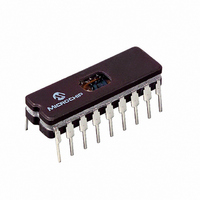
PIC16C717/JW
Description
IC MCU EPROM2KX14 A/D PWM 18CDIP
Manufacturer
Microchip Technology
Series
PIC® 16Cr
Datasheets
1.PIC16F818-ISO.pdf
(6 pages)
2.PIC16C770-ISO.pdf
(220 pages)
3.PIC16C770-ISO.pdf
(6 pages)
4.PIC16C770-ISO.pdf
(8 pages)
Specifications of PIC16C717/JW
Core Processor
PIC
Core Size
8-Bit
Speed
20MHz
Connectivity
I²C, SPI
Peripherals
Brown-out Detect/Reset, POR, PWM, WDT
Number Of I /o
15
Program Memory Size
3.5KB (2K x 14)
Program Memory Type
EPROM, UV
Ram Size
256 x 8
Voltage - Supply (vcc/vdd)
4 V ~ 5.5 V
Data Converters
A/D 6x10b
Oscillator Type
Internal
Operating Temperature
0°C ~ 70°C
Package / Case
18-CDIP (0.300", 7.62mm) Window
Lead Free Status / RoHS Status
Contains lead / RoHS non-compliant
Eeprom Size
-


PIC16C717/770/771
6.1.1
In this mode, Timer1 is being incremented via an exter-
nal source. Increments occur on a rising edge. After
Timer1 is enabled in Counter mode, the module must
first have a falling edge before the counter begins to
increment.
FIGURE 6-1:
FIGURE 6-2:
DS41120B-page 48
Note 1: When the T1OSCEN bit is cleared, the inverter and feedback resistor are turned off. This eliminates power drain.
T1CKI
(Initially high)
T1CKI
(Initially low)
RB6/T1OSO/T1CKI/P1C
RB7/T1OSI/P1D
Note: Arrows indicate counter increments.
First falling edge
of the T1ON enabled
TIMER1 COUNTER OPERATION
TIMER1 INCREMENTING EDGE
TIMER1 BLOCK DIAGRAM
Set flag bit
TMR1IF on
Overflow
First falling edge
of the T1ON enabled
TMR1H
T1OSC
TMR1
TMR1L
Oscillator(1)
T1OSCEN
Enable
Clock
Fosc/4
Internal
TMR1ON
on/off
TMR1CS
1
0
T1CKPS<1:0>
T1SYNC
Prescaler
1, 2, 4, 8
0
1
2
2002 Microchip Technology Inc.
Synchronized
clock input
Synchronize
SLEEP input
det
Related parts for PIC16C717/JW
Image
Part Number
Description
Manufacturer
Datasheet
Request
R

Part Number:
Description:
IC MCU EPROM 1KX14 A/D 18CDIP
Manufacturer:
Microchip Technology
Datasheet:

Part Number:
Description:
IC MCU OTP 1KX14 A/D 18DIP
Manufacturer:
Microchip Technology
Datasheet:

Part Number:
Description:
IC MCU OTP 1KX14 A/D 18SOIC
Manufacturer:
Microchip Technology
Datasheet:
Part Number:
Description:
IC MCU OTP 1KX14 A/D 18DIP
Manufacturer:
Microchip Technology
Datasheet:
Part Number:
Description:
IC MCU OTP 1KX14 A/D 18DIP
Manufacturer:
Microchip Technology
Datasheet:
Part Number:
Description:
IC MCU OTP 1KX14 A/D 18SOIC
Manufacturer:
Microchip Technology
Datasheet:
Part Number:
Description:
IC MCU OTP 1KX14 A/D 18SOIC
Manufacturer:
Microchip Technology
Datasheet:
Part Number:
Description:
IC MCU OTP 1KX14 A/D 18SOIC
Manufacturer:
Microchip Technology
Datasheet:
Part Number:
Description:
IC MCU OTP 1KX14 A/D 18DIP
Manufacturer:
Microchip Technology
Datasheet:

Part Number:
Description:
8-Bit CMOS Microcontrollers with A/D Converter
Manufacturer:
Microchip Technology
Datasheet:
Part Number:
Description:
8-Bit CMOS Microcontrollers with A/D Converter
Manufacturer:
Microchip Technology
Part Number:
Description:
8-Bit CMOS Microcontrollers with A/D Converter
Manufacturer:
Microchip Technology
Part Number:
Description:
8-Bit CMOS Microcontrollers with A/D Converter
Manufacturer:
Microchip Technology
Part Number:
Description:
8-Bit CMOS Microcontrollers with A/D Converter
Manufacturer:
Microchip Technology
Part Number:
Description:
8-Bit CMOS Microcontrollers with A/D Converter
Manufacturer:
Microchip Technology