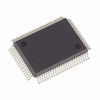
DS5002FMN-16 Maxim Integrated Products, DS5002FMN-16 Datasheet - Page 12

DS5002FMN-16
Manufacturer Part Number
DS5002FMN-16
Description
IC MPU SECURE 16MHZ IND 80-TQFP
Manufacturer
Maxim Integrated Products
Series
DS500xr
Datasheet
1.DS5002FPM-16.pdf
(25 pages)
Specifications of DS5002FMN-16
Core Processor
8051
Core Size
8-Bit
Speed
16MHz
Connectivity
EBI/EMI, SIO, UART/USART
Peripherals
Power-Fail Reset, WDT
Number Of I /o
32
Program Memory Type
SRAM
Ram Size
128 x 8
Voltage - Supply (vcc/vdd)
4.5 V ~ 5.5 V
Oscillator Type
External
Operating Temperature
-40°C ~ 85°C
Package / Case
80-MQFP, 80-PQFP
Processor Series
DS5002
Core
8051
Data Bus Width
8 bit
Program Memory Size
32 KB, 64 KB, 128 KB
Data Ram Size
32 KB, 64 KB, 128 KB
Interface Type
UART
Maximum Clock Frequency
16 MHz
Number Of Programmable I/os
32
Number Of Timers
2
Operating Supply Voltage
4.5 V to 5.5 V
Maximum Operating Temperature
+ 85 C
Mounting Style
SMD/SMT
3rd Party Development Tools
PK51, CA51, A51, ULINK2
Minimum Operating Temperature
- 40 C
Lead Free Status / RoHS Status
Contains lead / RoHS non-compliant
Eeprom Size
-
Program Memory Size
-
Data Converters
-
Available stocks
Company
Part Number
Manufacturer
Quantity
Price
Company:
Part Number:
DS5002FMN-16
Manufacturer:
Maxim Integrated
Quantity:
10 000
Company:
Part Number:
DS5002FMN-16+
Manufacturer:
Maxim Integrated Products
Quantity:
135
Company:
Part Number:
DS5002FMN-16+
Manufacturer:
Maxim Integrated
Quantity:
10 000
PIN
62
78
22
23
32
42
43
14
53
72
73
3
NAME
PROG
MSEL
CE1N
VRST
N.C.
CE4
PE1
PE2
PE3
PE4
SDI
PF
Active-Low Chip Enable 4. This chip enable is provided to access a fourth 32k block of
memory. It connects to the chip-enable input of one SRAM. When MSEL = 0, this signal is
unused. CE4 is lithium-backed and remains at a logic high when V
Active-Low Peripheral Enable 1. Accesses data memory between addresses 0000h and
3FFFh when the PES bit is set to a logic 1. Commonly used to chip enable a byte-wide real-
time clock such as the DS1283. PE1 is lithium-backed and will remain at a logic high when
V
Active-Low Peripheral Enable 2. Accesses data memory between addresses 4000h and
7FFFh when the PES bit is set to a logic 1. PE2 is lithium-backed and will remain at a logic
high when V
Active-Low Peripheral Enable 3. Accesses data memory between addresses 8000h and
BFFFh when the PES bit is set to a logic 1. PE3 is not lithium-backed and can be connected
to any type of peripheral function. If connected to a battery-backed chip, it will need additional
circuitry to maintain the chip enable in an inactive state when V
Active-Low Peripheral Enable 4. Accesses data memory between addresses C000h and
FFFFh when the PES bit is set to a logic 1. PE4 is not lithium-backed and can be connected
to any type of peripheral function. If connected to a battery-backed chip, it will need additional
circuitry to maintain the chip enable in an inactive state when V
Invokes the Bootstrap Loader on Falling Edge. This signal should be debounced so that
only one edge is detected. If connected to ground, the micro enters bootstrap loading on
power-up. This signal is pulled up internally.
This I/O pin (open drain with internal pullup) indicates that the power supply (V
fallen below the V
DS5002FP drives this pin to a logic 0. Because the micro is lithium-backed, this signal is
guaranteed even when V
externally. This allows multiple parts to synchronize their power-down resets.
This output goes to a logic 0 to indicate that the micro has switched to lithium backup.
This corresponds to V
even when V
current to isolate battery-backed functions from non-battery-backed functions.
Memory Select. This signal controls the memory size selection. When MSEL = +5V, the
DS5002FP expects to use 32k x 8 SRAMs. When MSEL = 0V, the DS5002FP expects to use
a 128k x 8 SRAM. MSEL must be connected regardless of partition, mode, etc.
Self-Destruct Input. An active high on this pin causes an unlock procedure. This results in
the destruction of Vector RAM, Encryption Keys, and the loss of power from V
should be grounded if not used.
Non-Battery-Backed Version of CE1. It is not generally useful since the DS5002FP cannot
be used with EPROM due to its encryption.
No Connection
CC
falls below V
CC
CC
falls below V
= 0V. The normal application of this signal is to control lithium-powered
LI
. Connect PE1 to battery-backed functions only.
CCMIN
CC
level and the micro is in a reset state. When this occurs, the
< V
12 of 25
CC
LI
= 0V. Because it is an I/O pin, it also forces a reset if pulled low
LI
. Connect PE2 to battery-backed functions only.
. Because the micro is lithium-backed, this signal is guaranteed
FUNCTION
CC
CC
< V
< V
CC
falls below V
LI
LI
.
.
CCO
. This pin
LI
.
CC
) has


