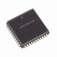
DS80C320-QCG/T&R Maxim Integrated Products, DS80C320-QCG/T&R Datasheet - Page 8

DS80C320-QCG/T&R
Manufacturer Part Number
DS80C320-QCG/T&R
Description
IC MCU HI SPEED 25MHZ 44-PLCC
Manufacturer
Maxim Integrated Products
Series
80Cr
Datasheet
1.DS80C323-QND.pdf
(38 pages)
Specifications of DS80C320-QCG/T&R
Core Processor
8051
Core Size
8-Bit
Speed
25MHz
Connectivity
EBI/EMI, SIO, UART/USART
Peripherals
Power-Fail Reset, WDT
Number Of I /o
32
Program Memory Type
ROMless
Ram Size
256 x 8
Voltage - Supply (vcc/vdd)
4.5 V ~ 5.5 V
Oscillator Type
External
Operating Temperature
0°C ~ 70°C
Package / Case
44-LCC, 44-PLCC
Processor Series
DS80C320
Core
8051
Data Bus Width
8 bit
Program Memory Size
64 KB
Data Ram Size
64 KB
Interface Type
UART
Maximum Clock Frequency
25 MHz
Number Of Programmable I/os
32
Number Of Timers
3
Operating Supply Voltage
4.25 V to 5.5 V
Maximum Operating Temperature
+ 70 C
Mounting Style
SMD/SMT
3rd Party Development Tools
PK51, CA51, A51, ULINK2
Minimum Operating Temperature
0 C
Lead Free Status / RoHS Status
Contains lead / RoHS non-compliant
Eeprom Size
-
Program Memory Size
-
Data Converters
-
Lead Free Status / Rohs Status
No
Available stocks
Company
Part Number
Manufacturer
Quantity
Price
Company:
Part Number:
DS80C320-QCG/T&RDS80C320-QCG/T&R
Manufacturer:
Maxim Integrated
Quantity:
10 000
DS80C320/DS80C323 High-Speed/Low-Power Microcontrollers
INSTRUCTION SET SUMMARY
All instructions in the DS80C320/DS80C323 perform the same functions as their 80C32 counterparts.
Their effect on bits, flags, and other status functions is identical. However, the timing of each instruction
is different. This applies both in absolute and relative number of clocks.
For absolute timing of real-time events, the timing of software loops will need to be calculated using the
Table 1. However, counter/timers default to run at the older 12 clocks per increment. Therefore, while
software runs at higher speed, timer-based events need no modification to operate as before. Timers can
be set to run at 4 clocks per increment cycle to take advantage of higher speed operation.
The relative time of two instructions might be different in the new architecture than it was previously. For
example, in the original architecture, the “MOVX A, @DPTR” instruction and the “MOV direct, direct”
instruction used two machine cycles or 24 oscillator cycles. Therefore, they required the same amount of
time. In the DS80C320/DS80C323, the MOVX instruction can be done in two machine cycles or eight
oscillator cycles, but the “MOV direct, direct” uses three machine cycles or 12 oscillator cycles. While
both are faster than their original counterparts, they now have different execution times from each other.
This is because in most cases, the DS80C320/DS80C323 use one cycle for each byte. The user concerned
with precise program timing should examine the timing of each instruction for familiarity with the
changes. Note that a machine cycle now requires just four clocks, and provides one ALE pulse per cycle.
Many instructions require only one cycle, but some require five. In the original architecture, all were one
or two cycles except for MUL and DIV.
8 of 38


