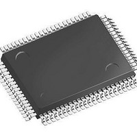
SAF-C161PI-L25F CA Infineon Technologies, SAF-C161PI-L25F CA Datasheet - Page 76

SAF-C161PI-L25F CA
Manufacturer Part Number
SAF-C161PI-L25F CA
Description
IC MCU 16BIT ROM/LESS TQFP-100-1
Manufacturer
Infineon Technologies
Series
C16xxr
Datasheet
1.SAF-C161PI-LM_CA.pdf
(82 pages)
Specifications of SAF-C161PI-L25F CA
Core Processor
C166
Core Size
16-Bit
Speed
25MHz
Connectivity
EBI/EMI, I²C, SPI, UART/USART
Peripherals
POR, PWM, WDT
Number Of I /o
76
Program Memory Type
ROMless
Ram Size
3K x 8
Voltage - Supply (vcc/vdd)
4.5 V ~ 5.5 V
Data Converters
A/D 4x10b
Oscillator Type
Internal
Operating Temperature
-40°C ~ 85°C
Package / Case
100-LFQFP
Data Bus Width
16 bit
Data Ram Size
3 KB
Interface Type
1xASC, 1xSSC, 1xl2C
Maximum Clock Frequency
25 MHz
Number Of Programmable I/os
76
Number Of Timers
5
Operating Supply Voltage
5 V
Maximum Operating Temperature
+ 85 C
Mounting Style
SMD/SMT
Minimum Operating Temperature
- 40 C
On-chip Adc
10 bit, 4 Channel
Packages
PG-TQFP-100
Max Clock Frequency
25.0 MHz
Sram (incl. Cache)
3.0 KByte
A / D Input Lines (incl. Fadc)
4
Program Memory
0.0 KByte
Lead Free Status / RoHS Status
Lead free / RoHS Compliant
Eeprom Size
-
Program Memory Size
-
Lead Free Status / Rohs Status
Details
Other names
F161PIL25FCAXT
SAF-C161PI-L25FCA
SAF-C161PI-L25FCAINTR
SAF-C161PI-L25FCATR
SAF-C161PI-L25FCATR
SAFC161PIL25FCAXT
SP000014363
SAF-C161PI-L25FCA
SAF-C161PI-L25FCAINTR
SAF-C161PI-L25FCATR
SAF-C161PI-L25FCATR
SAFC161PIL25FCAXT
SP000014363
Data Sheet
AC Characteristics
CLKOUT and READY (Standard Supply Voltage Range)
(Operating Conditions apply)
Parameter
CLKOUT cycle time
CLKOUT high time
CLKOUT low time
CLKOUT rise time
CLKOUT fall time
CLKOUT rising edge to
ALE falling edge
Synchronous READY
setup time to CLKOUT
Synchronous READY
hold time after CLKOUT
Asynchronous READY
low time
Asynchronous READY
setup time
Asynchronous READY
hold time
Async. READY hold time
after RD, WR high
(Demultiplexed Bus)
1) These timings are given for test purposes only, in order to assure recognition at a specific clock edge.
2) Demultiplexed bus is the worst case. For multiplexed bus 2TCL are to be added to the maximum values. This
adds even more time for deactivating READY.
The 2
The maximum limit for
A
and
1)
1)
C
refer to the next following bus cycle,
60
2)
must be fulfilled if the next following bus cycle is READY controlled.
Symbol
29
30
31
32
33
34
35
36
37
58
59
60
CC 40
CC 14
CC 10
CC –
CC –
CC 0 +
SR 14
SR 4
SR 54
SR 14
SR 4
SR 0
Max. CPU Clock
min.
= 25 MHz
A
74
F
refers to the current bus cycle.
40
–
–
4
4
10 +
–
–
–
–
–
0
+ 2
C
max.
+
A
F
+
A
2)
1 / 2TCL = 1 to 25 MHz
2TCL
TCL – 6
TCL – 10
–
–
0 +
14
4
2TCL +
14
4
0
Variable CPU Clock
min.
A
58
2TCL
–
–
4
4
10 +
–
–
–
–
–
TCL - 20
+ 2
+
F
max.
A
2)
+
A
C
&3,
1999-07
Unit
ns
ns
ns
ns
ns
ns
ns
ns
ns
ns
ns
ns


