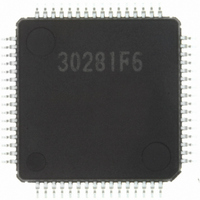
M30281F6HP#U5B Renesas Electronics America, M30281F6HP#U5B Datasheet - Page 11

M30281F6HP#U5B
Manufacturer Part Number
M30281F6HP#U5B
Description
IC M16C/28 MCU FLASH 48K 64LQFP
Manufacturer
Renesas Electronics America
Series
M16C™ M16C/Tiny/28r
Datasheet
1.M30280F6HPU9.pdf
(425 pages)
Specifications of M30281F6HP#U5B
Core Processor
M16C/60
Core Size
16-Bit
Speed
20MHz
Connectivity
I²C, IEBus, SIO, UART/USART
Peripherals
DMA, POR, PWM, Voltage Detect, WDT
Number Of I /o
55
Program Memory Size
48KB (48K x 8)
Program Memory Type
FLASH
Ram Size
4K x 8
Voltage - Supply (vcc/vdd)
2.7 V ~ 5.5 V
Data Converters
A/D 13x10b
Oscillator Type
Internal
Operating Temperature
-20°C ~ 85°C
Package / Case
64-LQFP
For Use With
R0K330290S000BE - KIT EVAL STARTER FOR M16C/29M30290T2-CPE - EMULATOR COMPACT M16C/26A/28/29M30290T2-CPE-HP - EMULATOR COMPACT FOR M16C/TINY
Lead Free Status / RoHS Status
Lead free / RoHS Compliant
Eeprom Size
-
Available stocks
Company
Part Number
Manufacturer
Quantity
Price
Part Number:
M30281F6HP#U5BM30281F6HP#D5
Manufacturer:
Renesas Electronics America
Quantity:
10 000
Part Number:
M30281F6HP#U5BM30281F6HP#U3
Manufacturer:
Renesas Electronics America
Quantity:
10 000
- Current page: 11 of 425
- Download datasheet (4Mb)
5. Reset ..............................................................................................................32
6. Processor Mode .............................................................................................41
7. Clock Generation Circuit ................................................................................44
8. Protection .......................................................................................................66
9. Interrupts ........................................................................................................67
5.1 Hardware Reset .............................................................................................................. 32
5.2 Software Reset ............................................................................................................... 33
5.3 Watchdog Timer Reset ................................................................................................... 33
5.4 Oscillation Stop Detection Reset .................................................................................... 33
5.5 Voltage Detection Circuit ................................................................................................ 35
7.1 Main Clock ...................................................................................................................... 51
7.2 Sub Clock ....................................................................................................................... 52
7.3 On-chip Oscillator Clock ................................................................................................. 53
7.4 PLL Clock ....................................................................................................................... 53
7.5 CPU Clock and Peripheral Function Clock ..................................................................... 55
7.6 Power Control ................................................................................................................. 56
7.7 System Clock Protective Function .................................................................................. 63
7.8 Oscillation Stop and Re-oscillation Detect Function ....................................................... 63
9.1 Type of Interrupts ............................................................................................................ 67
5.1.1 Hardware Reset 1 .................................................................................................... 32
5.1.2 Hardware Reset 2 .................................................................................................... 32
5.5.1 Low Voltage Detection Interrupt ............................................................................... 38
5.5.2 Limitations on Stop Mode ......................................................................................... 40
5.5.3 Limitations on WAIT Instruction ................................................................................ 40
7.5.1 CPU Clock ................................................................................................................ 55
7.5.2 Peripheral Function Clock(f
7.6.1 Normal Operation Mode ........................................................................................... 56
7.6.2 Wait Mode ................................................................................................................ 57
7.6.3 Stop Mode ............................................................................................................... 59
7.8.1 Operation when CM27 bit is set to "0" (Oscillation Stop Detection Reset) .............. 64
7.8.2
7.8.3 How to Use Oscillation Stop and Re-oscillation Detect Function ............................. 65
9.1.1 Software Interrupts ................................................................................................... 68
9.1.2 Hardware Interrupts ................................................................................................. 69
Operation when CM27 bit is set to "1" (Oscillation Stop and Re-oscillation Detect Interrupt) ....
1
, f
2
, f
8
, f
A-2
32
, f
1SIO
, f
2SIO
, f
8SIO
, f
32SIO
, f
AD
, f
C32
) ........... 55
64
Related parts for M30281F6HP#U5B
Image
Part Number
Description
Manufacturer
Datasheet
Request
R

Part Number:
Description:
KIT STARTER FOR M16C/29
Manufacturer:
Renesas Electronics America
Datasheet:

Part Number:
Description:
KIT STARTER FOR R8C/2D
Manufacturer:
Renesas Electronics America
Datasheet:

Part Number:
Description:
R0K33062P STARTER KIT
Manufacturer:
Renesas Electronics America
Datasheet:

Part Number:
Description:
KIT STARTER FOR R8C/23 E8A
Manufacturer:
Renesas Electronics America
Datasheet:

Part Number:
Description:
KIT STARTER FOR R8C/25
Manufacturer:
Renesas Electronics America
Datasheet:

Part Number:
Description:
KIT STARTER H8S2456 SHARPE DSPLY
Manufacturer:
Renesas Electronics America
Datasheet:

Part Number:
Description:
KIT STARTER FOR R8C38C
Manufacturer:
Renesas Electronics America
Datasheet:

Part Number:
Description:
KIT STARTER FOR R8C35C
Manufacturer:
Renesas Electronics America
Datasheet:

Part Number:
Description:
KIT STARTER FOR R8CL3AC+LCD APPS
Manufacturer:
Renesas Electronics America
Datasheet:

Part Number:
Description:
KIT STARTER FOR RX610
Manufacturer:
Renesas Electronics America
Datasheet:

Part Number:
Description:
KIT STARTER FOR R32C/118
Manufacturer:
Renesas Electronics America
Datasheet:

Part Number:
Description:
KIT DEV RSK-R8C/26-29
Manufacturer:
Renesas Electronics America
Datasheet:

Part Number:
Description:
KIT STARTER FOR SH7124
Manufacturer:
Renesas Electronics America
Datasheet:

Part Number:
Description:
KIT STARTER FOR H8SX/1622
Manufacturer:
Renesas Electronics America
Datasheet:

Part Number:
Description:
KIT DEV FOR SH7203
Manufacturer:
Renesas Electronics America
Datasheet:


