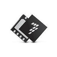
MC9S08SH16CTJ Freescale Semiconductor, MC9S08SH16CTJ Datasheet - Page 14

MC9S08SH16CTJ
Manufacturer Part Number
MC9S08SH16CTJ
Description
MCU 8BIT 16K FLASH 20-TSSOP
Manufacturer
Freescale Semiconductor
Series
HCS08r
Specifications of MC9S08SH16CTJ
Core Processor
HCS08
Core Size
8-Bit
Speed
40MHz
Connectivity
I²C, LIN, SCI, SPI
Peripherals
LVD, POR, PWM, WDT
Number Of I /o
17
Program Memory Size
16KB (16K x 8)
Program Memory Type
FLASH
Ram Size
1K x 8
Voltage - Supply (vcc/vdd)
2.7 V ~ 5.5 V
Data Converters
A/D 12x10b
Oscillator Type
Internal
Operating Temperature
-40°C ~ 85°C
Package / Case
20-TSSOP
Processor Series
S08SH
Core
HCS08
Data Bus Width
8 bit
Data Ram Size
1 KB
Interface Type
I2C, SCI, SPI
Maximum Clock Frequency
40 MHz
Number Of Programmable I/os
17
Number Of Timers
2
Operating Supply Voltage
5.5 V
Maximum Operating Temperature
+ 85 C
Mounting Style
SMD/SMT
3rd Party Development Tools
EWS08
Development Tools By Supplier
DEMO9S08SG32, DEMO9S08SG32AUTO, DEMO9S08SG8, DEMO9S08SG8AUTO, DEMO9S08SH32, DEMO9S08SH8
Minimum Operating Temperature
- 40 C
On-chip Adc
10 bit, 16 Channel
Cpu Family
HCS08
Device Core Size
8b
Frequency (max)
40MHz
Total Internal Ram Size
1KB
# I/os (max)
17
Number Of Timers - General Purpose
3
Operating Supply Voltage (typ)
3.3/5V
Operating Supply Voltage (max)
5.5V
Operating Supply Voltage (min)
2.7V
Instruction Set Architecture
CISC
Operating Temp Range
-40C to 85C
Operating Temperature Classification
Industrial
Mounting
Surface Mount
Pin Count
20
Package Type
TSSOP
Lead Free Status / RoHS Status
Lead free / RoHS Compliant
Eeprom Size
-
Lead Free Status / Rohs Status
Lead free / RoHS Compliant
Available stocks
Company
Part Number
Manufacturer
Quantity
Price
Part Number:
MC9S08SH16CTJR
Manufacturer:
FREESCALE
Quantity:
20 000
Section Number
11.2 External Signal Description .......................................................................................................... 173
11.3 Register Definition ........................................................................................................................ 173
11.4 Functional Description .................................................................................................................. 177
12.1 Introduction ................................................................................................................................... 183
12.2 External Signal Description .......................................................................................................... 186
12.3 Register Definition ........................................................................................................................ 187
12.4 Functional Description .................................................................................................................. 191
13.1 Introduction ................................................................................................................................... 193
13.2 External Signal Description .......................................................................................................... 196
13.3 Register Definition ........................................................................................................................ 196
14
11.1.4 Modes of Operation ........................................................................................................ 172
11.3.1 ICS Control Register 1 (ICSC1) ..................................................................................... 174
11.3.2 ICS Control Register 2 (ICSC2) ..................................................................................... 175
11.3.3 ICS Trim Register (ICSTRM)......................................................................................... 176
11.3.4 ICS Status and Control (ICSSC)..................................................................................... 176
11.4.1 Operational Modes.......................................................................................................... 177
11.4.2 Mode Switching .............................................................................................................. 179
11.4.3 Bus Frequency Divider ................................................................................................... 180
11.4.4 Low Power Bit Usage ..................................................................................................... 180
11.4.5 Internal Reference Clock ................................................................................................ 180
11.4.6 Optional External Reference Clock ................................................................................ 180
11.4.7 Fixed Frequency Clock ................................................................................................... 181
12.1.1 MTIM Configuration Information .................................................................................. 183
12.1.2 Features ........................................................................................................................... 185
12.1.3 Modes of Operation ........................................................................................................ 185
12.1.4 Block Diagram ................................................................................................................ 186
12.3.1 MTIM Status and Control Register (MTIMSC) ............................................................. 188
12.3.2 MTIM Clock Configuration Register (MTIMCLK) ....................................................... 189
12.3.3 MTIM Counter Register (MTIMCNT)........................................................................... 190
12.3.4 MTIM Modulo Register (MTIMMOD).......................................................................... 190
12.4.1 MTIM Operation Example ............................................................................................. 192
13.1.1 Features ........................................................................................................................... 195
13.1.2 Modes of Operation ........................................................................................................ 195
13.1.3 Block Diagram ................................................................................................................ 196
13.3.1 RTC Status and Control Register (RTCSC).................................................................... 197
13.3.2 RTC Counter Register (RTCCNT).................................................................................. 198
Real-Time Counter (S08RTCV1)
Modulo Timer (S08MTIMV1)
MC9S08SH32 Series Data Sheet, Rev. 2
Chapter 12
Chapter 13
PRELIMINARY
Title
Freescale Semiconductor
Page


