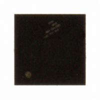
MC9S08QG8MFQE Freescale Semiconductor, MC9S08QG8MFQE Datasheet - Page 177

MC9S08QG8MFQE
Manufacturer Part Number
MC9S08QG8MFQE
Description
IC MCU 8K FLASH 8-DFN
Manufacturer
Freescale Semiconductor
Series
HCS08r
Datasheet
1.MC9S08QG8CDTER.pdf
(314 pages)
Specifications of MC9S08QG8MFQE
Core Processor
HCS08
Core Size
8-Bit
Speed
20MHz
Connectivity
I²C, SCI, SPI
Peripherals
LVD, POR, PWM, WDT
Number Of I /o
4
Program Memory Size
8KB (8K x 8)
Program Memory Type
FLASH
Ram Size
512 x 8
Voltage - Supply (vcc/vdd)
1.8 V ~ 3.6 V
Data Converters
A/D 4x10b
Oscillator Type
Internal
Operating Temperature
-40°C ~ 125°C
Package / Case
8-DFN
Processor Series
S08QG
Core
HCS08
Data Bus Width
8 bit
Data Ram Size
512 B
Interface Type
I2C, SCI, SPI
Maximum Clock Frequency
20 MHz
Number Of Programmable I/os
4
Number Of Timers
1
Maximum Operating Temperature
+ 125 C
Mounting Style
SMD/SMT
3rd Party Development Tools
EWS08
Development Tools By Supplier
DEMO9S08QG8E
Minimum Operating Temperature
- 40 C
On-chip Adc
10 bit, 4 Channel
For Use With
DEMO9S08QG8E - BOARD DEMO FOR MC9S08QG8
Lead Free Status / RoHS Status
Lead free / RoHS Compliant
Eeprom Size
-
Lead Free Status / Rohs Status
Details
- Current page: 177 of 314
- Download datasheet (6Mb)
12.1.1
The KBI features include:
12.1.2
This section defines the KBI operation in wait, stop, and background debug modes.
12.1.2.1
The KBI continues to operate in wait mode if enabled before executing the WAIT instruction. Therefore,
an enabled KBI pin (KBPEx = 1) can be used to bring the MCU out of wait mode if the KBI interrupt is
enabled (KBIE = 1).
12.1.2.2
The KBI operates asynchronously in stop3 mode if enabled before executing the STOP instruction.
Therefore, an enabled KBI pin (KBPEx = 1) can be used to bring the MCU out of stop3 mode if the KBI
interrupt is enabled (KBIE = 1).
During either stop1 or stop2 mode, the KBI is disabled. In some systems, the pins associated with the KBI
may be sources of wakeup from stop1 or stop2, see the stop modes section in the
chapter. Upon wake-up from stop1 or stop2 mode, the KBI module will be in the reset state.
12.1.2.3
When the microcontroller is in active background mode, the KBI will continue to operate normally.
12.1.3
The block diagram for the keyboard interrupt module is shown
Freescale Semiconductor
•
•
•
•
Up to eight keyboard interrupt pins with individual pin enable bits.
Each keyboard interrupt pin is programmable as falling edge (or rising edge) only, or both falling
edge and low level (or both rising edge and high level) interrupt sensitivity.
One software enabled keyboard interrupt.
Exit from low-power modes.
Features
Modes of Operation
Block Diagram
KBI in Wait Mode
KBI in Stop Modes
KBI in Active Background Mode
MC9S08QG8 and MC9S08QG4 Data Sheet, Rev. 5
Figure
12-2.
Keyboard Interrupts (S08KBIV2)
Modes of Operation
175
Related parts for MC9S08QG8MFQE
Image
Part Number
Description
Manufacturer
Datasheet
Request
R
Part Number:
Description:
Manufacturer:
Freescale Semiconductor, Inc
Datasheet:
Part Number:
Description:
Manufacturer:
Freescale Semiconductor, Inc
Datasheet:
Part Number:
Description:
Manufacturer:
Freescale Semiconductor, Inc
Datasheet:
Part Number:
Description:
Manufacturer:
Freescale Semiconductor, Inc
Datasheet:
Part Number:
Description:
Manufacturer:
Freescale Semiconductor, Inc
Datasheet:
Part Number:
Description:
Manufacturer:
Freescale Semiconductor, Inc
Datasheet:
Part Number:
Description:
Manufacturer:
Freescale Semiconductor, Inc
Datasheet:
Part Number:
Description:
Manufacturer:
Freescale Semiconductor, Inc
Datasheet:
Part Number:
Description:
Manufacturer:
Freescale Semiconductor, Inc
Datasheet:
Part Number:
Description:
Manufacturer:
Freescale Semiconductor, Inc
Datasheet:
Part Number:
Description:
Manufacturer:
Freescale Semiconductor, Inc
Datasheet:
Part Number:
Description:
Manufacturer:
Freescale Semiconductor, Inc
Datasheet:
Part Number:
Description:
Manufacturer:
Freescale Semiconductor, Inc
Datasheet:
Part Number:
Description:
Manufacturer:
Freescale Semiconductor, Inc
Datasheet:
Part Number:
Description:
Manufacturer:
Freescale Semiconductor, Inc
Datasheet:


