PBASIC2SX/P Parallax Inc, PBASIC2SX/P Datasheet - Page 6
PBASIC2SX/P
Manufacturer Part Number
PBASIC2SX/P
Description
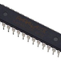
BASIC STAMP 2SX INTERPRETER CHIP
Manufacturer
Parallax Inc
Datasheet
1.27294.pdf
(8 pages)
Specifications of PBASIC2SX/P
Program Memory Type
EEPROM
Operating Supply Voltage
3 V to 5 V
Maximum Operating Temperature
+ 85 C
Mounting Style
Through Hole
Package / Case
DIP-28
For Use With
28803 - KIT BOARD OF EDU W/O PWR SUPP28300 - MOTHERBOARD BASIC STAMP 2PE28150 - BOARD OF EDUCATION28103 - KIT FULL BOARD OF EDUCATION
Lead Free Status / Rohs Status
Details
Other names
PBASIC2SX-28/DP


7. The next component to install is the ceramic resonator. The ceramic
8. Next, grab the electrolytic capacitor. It resembles a small cylinder with
9. Now find the PNP transistor (Q3); it looks like a black bead
10. Next you will install the 9-pin D-Sub connector. This is the only component that looks like it will
11. The last component to solder on is the voltage regulator, VR1. It is a relatively large plastic
12. Be sure you clean the board before you stuff the Basic Interpreter IC and the eeprom IC into
13. Visually inspect the board. Before applying power to it, repair any and all soldering errors and
14. Download and run the latest version of the program, STAMPW.exe, from either the CD or the
sales / technical support (916) 624-8333 fax (916) 624-8003
email: stamptech@parallaxinc.com
resonator looks like a coffee bean (although sometimes they are blue
instead of brown) with three metal legs sticking out from one side and
should be marked as “50.00” (50 MHz). This component is ‘polarity
insensitive’. That is to say that it doesn’t matter which way it is installed, it
will still work OK. Install the ceramic resonator where the ‘XTAL’ designator is.
two long legs emerging from one end. Be particularly careful when
installing this component. If it is installed backwards, it can pop like a
miniature fire cracker and emit a horrible stench after it is powered up.
The electrolytic capacitor will have the negative lead marked with one
or more ‘-’ signs. Install the leg NOT marked with the ‘-’ signs in the
hole closest to the ‘+’ sign in C1’s space on the pcb.
with three
silkscreen on the pcb will guide you as to how to orient this
component. There are two other components that closely
resemble the PNP transistor that you will be installing in this
step. Please note that the middle legs must be bent slightly
to accomodate the hole patterns for Q1, Q2, and Q3. Please
bend the middle leg of the PNP transistor (3906), and the
NPN transistors, (3904), as shown in the drawing above. Avoid excessive bending as this can
damage the component. Install the PNP transistor into Q3, and the NPN transistors into Q1,
and Q2.
plug into a serial cable. Install it on the top side of the pcb.
square with a metal tab protruding from the top. Install this with the metal tab closest to the 9-
pin D-Sub connector. This component, like the electrolytic capacitor, IS polarity sensitive and
MUST be installed correctly, lest ye suffer smoke and fire and the gnashing of teeth.
U1’s and U2’s respective sockets. That’s it ! You’ve done it! You’ve made your own stamp.
verify that all components have been installed in the proper locations and with the correct
orientation.
website. Connect the OEM BS2sx to a PC serial port and power it up. Please consult the
Basic Stamp manual, also available from either the CD or our website, for guidance on using
your BS2sx. Please select the BS2sx as the default stamp before attempting to identify or
download a program to your new BS2sx. You must also name the stamp program you wish to
download with a .bsx extension.
legs and bears the mark, “3906”. The white
OEM BS2sx
Rev 1.0
Page 2
Related parts for PBASIC2SX/P
Image
Part Number
Description
Manufacturer
Datasheet
Request
R

Part Number:
Description:
Microcontrollers (MCU) BASIC Stamp 2 DIP Interpreter Chip
Manufacturer:
Parallax Inc

Part Number:
Description:
BASIC STAMP 2 INTERPRETER CHIP
Manufacturer:
Parallax Inc
Datasheet:

Part Number:
Description:
Microcontroller Modules & Accessories DISCONTINUED BY PARALLAX
Manufacturer:
Parallax Inc

Part Number:
Description:
BOOK UNDERSTANDING SIGNALS
Manufacturer:
Parallax Inc
Datasheet:


Part Number:
Description:
COMPETITION RING FOR SUMOBOT
Manufacturer:
Parallax Inc
Datasheet:


Part Number:
Description:
TEXT INFRARED REMOTE FOR BOE-BOT
Manufacturer:
Parallax Inc
Datasheet:
Part Number:
Description:
Microcontroller Modules & Accessories DISCONTINUED BY PARALLAX
Manufacturer:
Parallax Inc
Part Number:
Description:
BOOK UNDERSTANDING SIGNALS
Manufacturer:
Parallax Inc
Datasheet:
Part Number:
Description:
BOARD EXPERIMENT+LCD NX-1000
Manufacturer:
Parallax Inc
Datasheet:
Part Number:
Description:
IC MCU 2K FLASH 50MHZ SO-18
Manufacturer:
Parallax Inc
Datasheet: